
Changing flow direction for optimal heat exchanger performance
October 26, 2016 | By John Siegenthaler
Many systems with renewable energy heat sources also have large thermal storage tanks. Examples include systems using biomass boilers and solar thermal collectors.
I call these heat sources “wild” since they can operate over a wide range of conditions and often at temperatures significantly higher than required by modern low-temperature hydronic distribution systems. That word “wild” might seem a bit strong, but I use it to emphasize that managing these heat sources within a system is very different from just turning a gas-fired boiler or some other conventional heat source on and off.
Significant thermal storage is also used in systems with electric boilers operating on off-peak rates or combined heat and power systems. These heat sources can also produce high water temperatures, which mandate one or more mixing assemblies be used between the thermal storage tank and any low temperature hydronic distribution system.
When storage volume requirements reach a few hundred gallons, some designers look to unpressurized thermal storage tanks as being less expensive on a dollar per gallon basis, and easier to install compared to pressure-rated steel tanks. In some cases an unpressurized thermal storage tank, which ships in a “knock-down” configuration, is the only practical option if the tank has to pass through a narrow door into an existing basement or mechanical room.
In limited applications, it is possible to route water from unpressurized thermal storage tanks directly to a heat source or hydronic distribution system. However, this requires specific components, careful design and details that are not common in closed-loop hydronic systems.
One requirement is that all wetted components must be suitable for open-loop systems. Since the unpressurized tank is vented to the atmosphere, the water has a “connection” to a virtually unlimited supply of oxygen. It will absorb and release oxygen molecules based on temperature and pressure. Some of those oxygen molecules will be carried through wetted portions of the system, and oxygen combined with iron does not lead to good results.
To avoid inevitable corrosion, all wetted surfaces in open hydronic systems must be nonferrous. This usually implies the use of materials such as copper, copper alloys (brass and bronze), stainless steel or polymers such as PEX. No ferrous metals such as carbon steel or cast-iron should be used in any open-loop hydronic system.
That last sentence precludes direct flow between any biomass boiler with a carbon steel heat exchanger, which is by far the most common type of biomass boiler construction. It also should preclude the use of any cast-iron circulators. This point is clearly documented by circulator manufacturers but, unfortunately, it is not always adhered to since cast iron circulators are significantly less expensive than those made of bronze or stainless steel. Open-loop designs also preclude the use of standard steel expansion tanks and steel panel radiators.
The restrictions associated with open-loop design often lead designers to specify a heat exchanger between the water in the unpressurized thermal storage tank and closed-loop circuits that add or remove heat from the tank.
One of the most common heat exchangers used in combination with large unpressurized thermal storage tanks is a helical copper coil. In some systems, one coil heat exchanger is used to dissipate heat from the heat source into the tank’s water. Another coil is used to extract heat from the tank and send it to the load. The connections to the coils are typically routed through the tank walls just above the maximum height water line. This reduces the potential for leakage through the tank penetrations.
OPPOSING DIRECTIONS
To attain maximum heat transfer from a heat exchanger, it is important that the fluids exchanging heat flow in opposite directions. This is called “counterflow” heat exchange. It provides the highest average water temperature difference between the two fluids.
Figure 1 shows how counterflow heat exchange is achieved when two coils, one for heat input and the other for heat extraction, are used in an unpressurized thermal storage tank.
The coil on the left is dissipating heat into the tank.
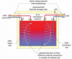
Figure 1
Hot water enters the top of the coil and passes downward. This is opposite to the natural convection flow within the tank, where heated water rises due to decreasing density. The coil on the right is extracting energy from the tank. Cooler water returning from the distribution system is sent to the bottom of the coil and flows upward. This is opposite to the direction of the tank water movements, which is sinking due to increasing density as it cools.
TWO INTO ONE
Some designer wants to use a single coil for heat input to the tank and heat extraction from the tank. If flow passes through the coil in only one direction, counterflow cannot be achieved in both heat dissipation and heat absorption modes. This will compromise performance.
One solution is to change the flow direction depending on the operating mode of the coil: top-to-bottom flow when adding heat to the tank and bottom-to-top flow when extracting heat.
There are several possible ways to reverse flow through the coil. One approach is shown in Figure 2.
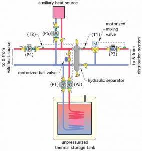
Figure 2
This arrangement uses two temperature-controlled (e.g., “setpoint”) circulators, (P1) and (P2). They face each other as far as flow direction is concerned. Only one circulator operates at a time, and neither contains a check valve. The operating circulator pushes flow through the coil and backward through the volute of the non-operating circulator.
Circulator (P1) monitors the temperature of sensor (T1). If the wild heat source circulator (P4) is off and a heating demand occurs, circulator (P3) and the mixing valve controller are turned on. Flow passes by sensor (T1). If the temperature at sensor (T1) is below a minimum setpoint value, the speed of circulator (P1) increases to drive flow upward within the coil heat exchanger, through the volute of circulator (P2) and into the hydraulic separator. The latter uncouples the flow dynamics of circulator (P1) from those of (P3). If circulator (P1) reaches maximum speed and flow from the coil is unable to meet the required temperature at (T1), an auxiliary heat source can be turned on.
A time delay should be allowed between a call for heat from the distribution system and activation of the auxiliary heat source. This allows the variable-speed pump time to ramp up if necessary, and have its turn at trying to produce the required supply water temperature before resorting to auxiliary energy.
Be sure your controls do not allow the auxiliary heat source to inadvertently send heat produced by the auxiliary heat source back to storage. The simplest way to do this is to interrupt power to circulator (P1) and (P2) whenever the auxiliary heat source is on.
If the wild heat source is operating at the same time as the load and the temperature at sensor (T2) climbs a few degrees above the required supply water temperature, circulator (P2) is enabled. It ramps up speed based on its temperature settings to push flow downward through the coil. Heat that is more than what the distribution system needs is routed into thermal storage.
Both (P1) and (P2) can be off if heat from the wild heat source is just sufficient to meet the required supply water temperature. This allows heat to fully bypass thermal storage, which can be beneficial when recovering loads from setback conditions.
I have shown a motorized ball valve in the coil circuit, which would close whenever circulator (P1) or (P2) is not operating. Since there cannot be any check valves in the coil circuit, this valve prevents slight but undesirable flow due to buoyancy differences and very small pressure differentials through the hydraulic separator and its headers. A ball valve is best since it has the same flow characteristics in either flow direction.
If the wild heat source is on and there is no call for heating from the load, circulator (P2) is on, circulators (P1), (P3) and (P5) are off, and the auxiliary heat source is off. All heat produced by the wild heat source is directed into thermal storage.
Accomplishing the above sequences will require some hard-wired or programmable control logic.
BAFFLING
If the system is designed around primary/secondary piping, it is also possible to reverse the flow direction through a heat exchanger coil using a cross fitting with a brazed-in baffle plate, as shown in Figure 3.
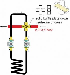
Figure 3
The cross fitting produces the same pressure at the beginning and end of the coil circuit. Thus, there is virtually no tendency for flow to develop in the coil circuit unless one of the circulators is operating. The baffle plate prevents what would otherwise be significant mixing due to flow momentum entering the upper connection of the cross and exiting the lower connection.
To my knowledge, there is no commercially available fitting with the geometry shown in Figure 3. If you want to use this, you will have to fabricate your own. It should not be too difficult if you can trim some flat copper or brass plate stock to the proper size and braze it down the centreline of the fitting.
Another detail I would recommend is the use of a time delay relay with a delay-on-make function in the circuit supplying the two circulators on the coil circuit. The idea is to allow both circulator impellers to fully stop before turning on either circulator. A nominal five-to 10-second delay should suffice.
Finally, I do not recommend using circulators with permanent magnet motors for the coil circuits shown in the figures. Reverse flow through the unpowered circulator may spin the impeller in reverse and thus cause the permanent magnet rotor to spin within the stator coils. This is likely to generate unwanted electrical feedback.
This article illustrates unique application details made possible through modern hydronics. Add these details to your bag of tricks; perhaps you will come across a situation where they can be applied.
John Siegenthaler, P.E., is a mechanical engineering graduate of Rensselaer Polytechnic Institute and a licensed professional engineer. www.hydronicpros.com

