
CO2 gets a second life-Part II
May 11, 2016 | By Dave Demma
The current market drivers that have given CO2, which was a relatively forgotten refrigerant for decades, a second life were discussed in HPAC March 2016. As a review, those drivers are: environmental properties (GWP and ODP); energy efficiency; safety (flammability and toxicity); cost; and availability.
In addition, the point was made that while there are some differences between refrigeration systems utilizing HCFC/HFC based refrigerants and those using CO2 as a refrigerant, there are still many similarities. Most importantly, regardless of the refrigerant in use, we are still transferring heat from the refrigerated space to the refrigerating medium. See the sidebar for some CO2 facts and relevant definitions.
Every substance (including all refrigerants) has a critical point. However, the commonly used refrigerants never come close to conditions where the system is operating near the critical point. For example, the critical temperature for R-22 is 205.1F.
To put this into practical terms, if a condition ever existed in an R-22 system where the saturated condensing temperature was at 205.1F, the system high side pressure would need to be 723.7 PSIA for a change of state (vapour to liquid) to occur. This condition is never going to happen in an R-22 system.
On the other hand, the critical temperature for CO2 is 87.9F, with the critical pressure at ~1055 PSIG. So, a CO2 system operating with an air cooled condenser, selected with a 10F TD, will reach its critical temperature when the outdoor ambient temperature reaches 77.9F. That does not allow too many locations to use CO2 without planning for transcritical operation.
Now, for the technician who visits a CO2 system in a supermarket for the first time, there are a few things that might stand out as being different than the typical HCFC/HFC system.
DIFFERENCES TO BE AWARE OF
1) While CO2 pressures are higher than those experienced with HCFC/HFC refrigerants, this is not the first refrigerant to enter the marketplace with substantially higher pressures than the industry’s mainstay refrigerants. The most recent example of this would be the higher pressures seen in an R-410A system as compared to an R-22 system. While it is not of the same magnitude as the increase between CO2 and R-404A, it is still a good example to illustrate that it is not unheard of to see a new refrigerant introduced with substantially higher pressures than the refrigerant it is meant to replace.
2) At a given saturation temperature, the CO2 pressure will be substantially higher than HCFC/HFC refrigerants. For example, at a -20F SST, the corresponding pressure will be 200 PSIG. Because of the higher pressures, you may see Type K copper, steel, stainless steel, or hybrid copper-steel piping, depending on the application. For example, the maximum allowable working pressure for the CO2 LT Secondary system is 400 PSIG. This would be the rating for the system relief valves. As such, the copper tubing will need to have a MAWP rating of at least 400 PSIG. The 1-5/8’’ and 2-1/8’’ Type L copper tubing does not meet that rating, requiring Type K to be used for those two sizes.
3) The CO2 might be used as a secondary heat transfer fluid.
4) Insulation wall thickness will be one inch in mild conditions (80F dry bulb, 50 per cent RH), 1-1/2 inch in normal conditions (85F dry bulb, 70 per cent RH) and two inch in severe conditions (90F dry bulb and 80 per cent RH).
5) Piping in display cases must be insulated.
6) Available in several different purity grades (as opposed to a single grade for HCFC/HFC refrigerants). The Coleman Grade, with a purity of 99.99 per cent, is the recommended minimum grade for refrigeration applications.
7) CO2 has a greater volumetric cooling capacity as compared to commonly used HFCs. For example, in a -20F application, R-404A has a latent heat of vaporization of 81 Btu/lb-min. As a comparison, in the same application CO2 has a latent heat of vaporization of 130 Btu/lb-min. The resulting mass flow requirement for CO2 will be approximately 38 per cent less, with the benefit of smaller compressor displacement and smaller pipe sizes.
8) Due to the high operating pressures you will see pressure relief valves everywhere. Anyplace in the system where liquid CO2 could be trapped with an isolation valve closure will require a relief valve piped in parallel with that valve. This allows a flow path for the potential high pressure CO2 in the isolated portion of the system to vent back to the main receiver vessel.
9) System charging: After evacuating, break system vacuum with vapour only. The triple point occurs at 75 PSIG. Charging liquid into a system which is at a pressure less than 75 PSIG will allow triple point conditions, meaning that some portion of the liquid will turn into a solid. You do not want dry ice inside the system piping. To be safe, the system should be pressurized to somewhere between 200 PSIG to 250 PSIG to avoid this scenario.
SYSTEMS IN THE FIELD
There are four types of CO2 systems that might be present in a new supermarket.
CO2 Secondary – Liquid Overfeed System
This system will utilize a separate direct expansion system, whose purpose is to maintain a secondary heat transfer fluid at a specific temperature. It is similar in concept to chiller system cooling down propylene glycol, which is then pumped to the various display cases and walk-in boxes, and used as the medium to transfer heat from those refrigerated spaces. The obvious difference being that CO2 has replaced the propylene glycol as the secondary fluid.
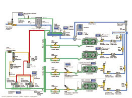
Figure 5 courtesy Sporlan Valve
Why use CO2 for this application?
Glycol has been used with success as a secondary fluid in medium temperature applications. While a second state of heat transfer will add some inefficiency, because the chiller negates pumping refrigerant to each display case and walk-in box, it does allow a substantial reduction in refrigerant charge. Unfortunately, glycol is not suitable as a secondary fluid for low temperature applications. So, this method of reducing the refrigerant charge has not been an option for low temperature systems.
CO2 allows secondary systems to become a viable option for low temperature applications. In addition, as opposed to the sensible heat transfer process which propylene glycol offers, CO2 offers the added heat transfer benefit of a fluid experiencing a change of state, which makes it a more efficient process. This benefit, plus the fact that CO2 has a greater volumetric cooling capacity, will allow for the use of significantly smaller pipe sizes.
Figure 5 shows a typical piping/component diagram for a CO2 secondary – liquid overfeed system. This being a cascade system, an HFC system will provide the heat transfer capacity necessary to condense the CO2 vapour into a liquid. One unique thing about this cascade system is that the lower cascade (the CO2 portion) does not utilize a compressor.
The liquid vapour separator receives the liquid/vapour mixture returning from the evaporators and separates the two phases in the vessel. Liquid from the bottom of the vessel enters the pump inlet, which provides the necessary pressure differential to supply liquid CO2 to the various evaporators connected to the system. As is the case with any other refrigeration system, a main liquid filter-drier will be utilized to remove harmful contaminants from the CO2. From there, the CO2 enters a liquid header, where individual liquid circuits will supply CO2 to each evaporator.
This is a liquid overfeed system where the CO2 flowing to the evaporators is already at the design SST. As such, no expansion device is required. In addition, the evaporators are circuited for the overfeed application. A solenoid valve at the inlet of the evaporator, controlled by either a standalone temperature controller, or the system’s central energy management controller, will regulate the flow of CO2 to each evaporator.
The solenoid valve coil will be energized when the temperature is above the set-point, which allows the valve to open. Liquid CO2 will flow through the evaporator, changing state as it absorbs heat from the refrigerated space. A mixture of liquid and vapour CO2 will flow back to the liquid vapour separator, with the liquid settling to the bottom and the vapour rising to the top. The cooler temperature occurring in the cascade evaporator/condenser will facilitate the flow of vapour from the separator to the condenser, resulting in a change of state from vapour to liquid, replenishing the liquid supply in the separator.
CO2 LT Direct Expansion Cascade – Subcritical
Think of this type of system as a typical vapour compression cycle with CO2 as the refrigerant utilized in the system. The only difference between a standard vapour compression cycle and the DX Cascade – Subcritical system is the fact that the heat transfer capacity necessary to condense the high temperature/high pressure vapour leaving the compressor into a high pressure/high temperature liquid is provided by an HFC refrigeration system, with the heat transfer taking place in a cascade evaporator/condenser. See system diagram in Figure 6.
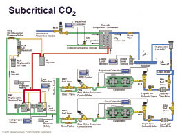
Figure 6 courtesy Sporlan Valve
Starting at the compressor: low temperature/low pressure vapour flows from the evaporators to the suction manifold, where it is then dispersed to whichever compressors happen to be operating at any given time. The compressors will compress the vapour, with a high temperature/high pressure vapour exiting the compressor. As common in a typical HFC multi-compressor rack, the discharge vapour flows to an oil separator before entering the condenser.
Again, the main difference in this system is that rather than a traditional condenser (air cooled, water cooled or evaporative condenser), the discharge vapour enters the cascade evaporator/condenser. Here the HFC system provides the heat transfer capacity necessary to condense the CO2 discharge vapour mass flow into a liquid. From here on, the system is nearly identical to a standard HFC system, with the liquid refrigerant flowing into a receiver, through a filter-drier and sight glass, then onto a liquid header. Here the individual system branches are supplied liquid as necessary. Electric expansion valves have become a standard feature in LT CO2 applications, taking the high temperature/high pressure liquid and allowing it to experience a pressure drop to bring the liquid to the design SST. The liquid vapour mixture enters the evaporator, absorbing heat from the refrigerated space, and fully changing state into a vapour before the evaporator outlet. In the diagram in Figure 6, an electric suction line regulator is shown as the method for maintaining constant discharge air temperature.
CO2 MT liquid overfeed/LT DX cascade – subcritical
The system diagram in Figure 7 shows this hybrid system, which is a combination of the two previously discussed systems: the CO2 secondary liquid overfeed system and the CO2 LT direct expansion cascade system.
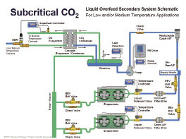
Figure 7 courtesy Sporlan Valve
The addition of the MT liquid overfeed portion requires the receiver to be of the liquid/vapour separator design. Liquid from the separator is pumped to both the LT and MT evaporator systems, with the MT operating as flooded evaporators and the LT operating as DX evaporators. The liquid/vapour mixture leaving the MT evaporators and the discharge vapour leaving the LT compressors are piped together via a tee, and then flow into the liquid/vapour separator. From here, vapour condensation is accomplished as the lower temperature in the cascade evaporator/condenser draws the vapour from the top of the separator.
CO2 booster – subcritical/transcritical system
The final system is the grand-daddy of sustainability, as it eliminates any need for any refrigerant other than CO2. As such, in ambient conditions where the resulting saturated condensing temperature will be greater than 87.9F the system must operate in the transcritical region. Since the CO2 will not exist as a liquid above the critical point, this presents a challenge that must be dealt with by different system design/components, as shown in Figure 8.
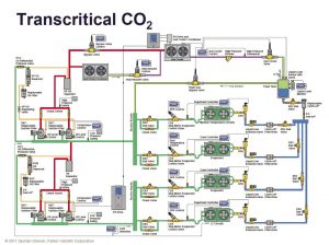
Figure 8 courtesy Sporlan Valve
This system is a two stage (compound) compression system, which in principle is not unlike the many R-22 two-stages that saw use after R-502 was phased out. The idea is that compressing the vapour from the low temperature evaporator systems in two stages allows for greater compressor efficiency by reducing the operating compression ratio of all compressors.
Vapour from the LT evaporator systems enters the LT compressors, which raise the low pressure to an intermediate pressure corresponding with the MT vapour pressure. The discharge vapour from the LT compressors flows through an oil separator and then enters the suction manifold to the MT compressors. The vapour leaving the MT evaporator systems joins the LT discharge vapour here. The entire system mass flow then enters the MT compressors. The discharge vapour leaving the MT compressors will first flow through an oil separator before entering the condenser gas cooler. The word condenser, with the strike through it, is there to illustrate that we now have a component with a different name, as in a transcritical condition the high temperature/high pressure vapour does not condense into a liquid.
Now, if the ambient conditions are such that the SCT is less than 87.9F, the CO2 vapour will indeed condense into a liquid. In this condition, the system will operate similarly to a typical vapour compression cycle, with the liquid leaving the gas cooler flowing into the receiver, and supplying the liquid header as needed. But for those times when the SCT is above 87.9F, the gas cooler transfers heat from the discharge vapour without a change of state taking place. This “neither liquid or vapour” mixture enters the flash tank, where the “flash tank bypass valve” will vent the high pressure to the suction manifold of the MT compressors. This allows sufficient reduction in pressure/temperature to move below the critical point, and allow the CO2 to revert to a saturated condition with both liquid and vapour phases present. From here, the liquid is supplied to the liquid header, supplying liquid to the various liquid feeds to each evaporator system as needed.
There are a few problems with the transcritical application: due to the higher condensing temperature and pressure, the higher compression ratio results in a less efficient compression process; the refrigerant quality (per cent vapour) after the expansion process is greater in the transcritical system, meaning that greater mass flow is required to provide the same mass flow of liquid at the evaporator inlet; and some amount of MT compressor capacity is dedicated to bringing the transcritical refrigerant mass in the flash tank back into a subcritical state. These have the combined effect of reducing the system efficiency, as this requiring extra compressor capacity to meet the design load condition, above and beyond what would be required for operation during the subcritical condition.
Dave Demma holds a degree in refrigeration engineering and worked as a journeyman refrigeration technician before moving into the manufacturing sector where he regularly trains contractor and engineering groups. He can be reached at ddemma@uri.com.
CO2 facts
- GWP = 1
- EPA SNAP (Significant New Alternatives Policy) approved
- ASHRAE A1 Classification (non-flammable/non-toxic)
- High volumetric cooling capacity compared to other refrigerants
- Low Viscosity (low pressure loss and lower pump HP requirement)
- High heat transfer coefficient
- Compatible with most materials
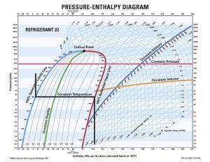
Figure 1 courtesy Sporlan Valve
DEFINITIONS
Critical Point: The point on a
phase diagram at which the liquid phase and vapour phase of a substance have the same density (meaning they are indistinguishable). See Figures 1 and 2.
Critical Temperature: The maximum temperature at which a vapour can be converted into a liquid by increasing
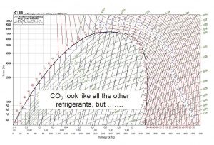
Figure 2
the vapour’s temperature. If the vapour is above the critical temperature, it cannot exist in the liquid state.
Critical Pressure: The pressure required to liquefy a gas at its critical temperature.
Triple Point: The temperature and
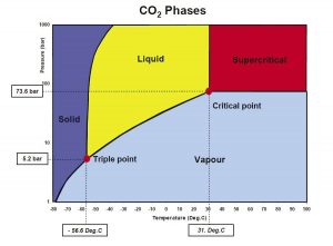
Figure 3
pressure at which the solid phase, liquid phase and vapour phase of a pure substance can coexist in equilibrium. See Figure 3.
Sublimation: The transition of a substance from the solid phase directly into the vapour phase. Sublimation occurs at temperatures and pressures below the triple point.
Subcritical: CO2 systems where the high side pressure is below the critical temperature (87.9F) and critical
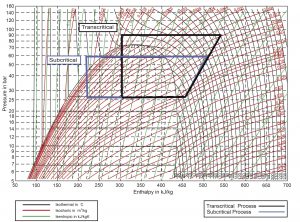
Figure 4 courtesy Emerson
pressure (~1055 PSIG).
Transcritical: CO2 systems that are designed to operate at pressures above the critical pressure of ~1055 PSIG. See Figure 4.
More System-Related Definitions
- Direct expansion: A refrigeration system, which includes a compressor, condenser, evaporator coil and some variety of expansion device.
- Primary refrigerant: A refrigerant that is used to lower the temperature of a secondary heat transfer fluid. For example, R-404A, R-507, R-22 could all be applied as a primary refrigerant.
- Secondary heat transfer fluid: A fluid used to transfer heat from the refrigerated space to the primary refrigerant.
- Single-phase secondary heat transfer fluid: A secondary fluid that absorbs heat by experiencing a sensible heat gain (temperature increase, but no change of state)
- Two-phase secondary heat transfer fluid: A secondary fluid that absorbs heat by experiencing a latent heat gain, resulting in a change of state.
- Cascade system: A system having two (or more) refrigerant circuits, where the evaporator of one circuit provides the heat transfer capacity necessary to accomplish condensing in the second circuit. The cascade evaporator/condenser will typically be of the brazed plate heat exchanger type.
- Upper Cascade: The refrigerant circuit in the cascade system that provides heat transfer capacity to the condenser in the second circuit. The heat transferred to the refrigerant in this system is rejected to some type of heat sink, typically an air cooled condenser, evaporative condenser, or water cooled condenser.
- Lower Cascade: The refrigerant circuit in a cascade system that transfers heat from the refrigerated spaces and transfers that heat to the upper cascade.

