Control logic for fluid temperature control
August 22, 2016 | By Mike Miller
We come across so many different types of terminology in our industry that not everyone is fully aware of their meanings. The following is some of the most basic control logic terminology with a short explanation of what each means and how they apply in hydronic system controls.
FLUID TEMPERATURE CONTROL LOGIC
Fluid temperature control is crucial in today’s advanced hydronic heating systems, not only to increase overall system efficiencies, but also to increase the overall comfort level within a system. Fixed water temperature control is still applicable in process applications, however for fluid temperature control provided to a heating terminal unit, it should be a thing of the past.
OUTDOOR RESET
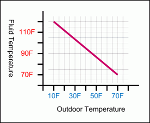
Outdoor reset refers to adjusting the fluid temperature provided to the system based on outdoor temperature change to match the changing building load. In most cases, this is done based on a ratio or heating curve that can be calculated using the design supply water temperature (DST – warmest fluid temperature required at the design day, also known as worst condition), warm weather outdoor temperature (WWODT –or warm weather shut down) and design outdoor temperature (DOT – coldest outdoor air temperature). See Figure 1 for an example of a high mass radiant floor heating system. The DST number will vary depending on type of terminal unit chosen to heat the building.
This calculated ratio references the amount of fluid temperature change per 1F outdoor air temperature change.
Using the same example as in Figure 1, should the outdoor air temperature change from DOT to 50F, the desired fluid target temperature would be 86.7F:
((WWODT–Outdoor air temperature) x Reset ratio) + WWODT = target).
On a graphical front, using this same formula, a heating curve can be drawn and this very same example is depicted in Figure 2.
OUTDOOR RESET CURVE SHIFT FOR SETBACK AND BOOST
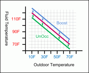
Since outdoor reset is matching the fluid temperature provided to the load of the building based on outdoor air temperature, the same logic can be applied to achieve building temperature setback at night, or other periods where the building is unoccupied, simply by reducing the fluid temperature below what is required during occupancy. Most leading controllers on the market will provide an Unoccupied scheduling feature through integral timers, or the ability to connect external timers. During unoccupied periods, the controllers would parallel shift the heating curve downward thus reducing the supply fluid temperature to the building to achieve building air temperature setback.
Alternatively, this same parallel shift logic is applied when the controller comes out of setback from unoccupied periods to achieve a boost and faster recovery of the building when it resumes normal occupancy conditions by shifting the heating curve
above its normal for a period of time that can either be applied through control logic based on outdoor temperature or simply a timed function. See Figure 3 for an example of a parallel shift.
ON/OFF FLUID TEMPERATURE CONTROL WITH FIXED DIFFERENTIAL
With modulating generation equipment (modulating boilers, mixing valves, injection pumps, and so on) On/Off fluid temperature control no longer applies, as shown in the modulating and floating control examples discussed later.
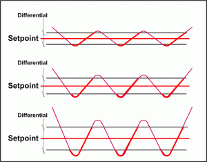
However, on/off generation equipment (on/off boilers, modulating boilers at or below minimum modulation output, heat pumps, on/off injection valves/pumps, and so on) are operated using On/Off control logic to maintain a desired setpoint. In most cases, an On/Off Differential is applied that is split half below and half above the target. This differential is in place in order to eliminate short cycling of the equipment. For example, if a setpoint is 120F and the chosen differential is 20F, then the equipment is turned ON at setpoint – diff (10F) and turned OFF at setpoint + diff (10F), effectively cycling the generation equipment
between 110F and 130F fluid temperature. See Figure 4 for a graphical example of an on/off differential.
ON/OFF FLUID TEMPERATURE CONTROL WITH AUTOMATICALLY ADJUSTED DIFFERENTIAL
Some of today’s most sophisticated controllers can apply a differential that automatically varies based on the load, using some additional PID logic (further explained below). In order to maximize operating efficiencies, an adequate balance
must be maintained between the lowest amount of temperature swings, while minimizing short cycling of the equipment at all times. Typically, when the load is high, a differential can be lower as the generation equipment is more effectively loaded. When the load is low, then the generation equipment has much greater capacity than the building requires and the differential should be larger in order to minimize or eliminate short cycling to extend its life cycle. Common automatically adjustable differentials range between two and 42F. See Figure 5 for graphical auto differential example.
FLOATING ACTION TYPE MIXING OUTPUT
Floating action type mixing refers to a motorized mixing device, often two-, three- or four-way mixing valves where the motor is actuated using most commonly either 24Vac or 120Vac. The voltage is applied for the motor to drive in either the open or the close position. When no voltage is applied to the motor, the valve remains in its current position. Most often, the time component and the dead band, as well as the operating band (not to be confused with On/Off Differential) is calculated using PI logic and the motors actuation speed from fully open to fully closed. Figure 6 shows how the controller pulses the floating action type motor either open or closed depending on where the temperature fluctuates.
When the temperature is within the dead band, the motor remains off, keeping the valve in its current position. If the temperature fluctuates above the setpoint and is within the operating band, then the valve is modulated/pulsed close as shown in this example.
When the temperature fluctuates below the desired setpoint and is within the operating band, then the valve is pulsed open as shown. Should the temperature fluctuate outside of the operating band, the motor will either open or close continuously until the temperature settles again within the band.
Floating action is one of the more cost effective and easier to implement control options available, but it is often also slower responding than a modulating output may be. Most floating action type motors take between 90-120 seconds to go from fully open to fully closed, but in high mass hydronic heating fluid temperature control systems it is sufficient.
MODULATING MIXING OUTPUT
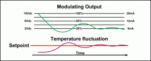
Modulating mixing devices generally have the capability to achieve much more accurate and faster temperature control than that of the floating action type. Modulating is often a requirement for low mass, fast reacting systems or process applications. Modulating devices can also still be two-, three- or four-way mixing valves, or even injection pumps. Modulating devices also include generation equipment, such as modulating boilers. Modulating signals are commonly either a small voltage between 0-10Vdc (2-10Vdc) or small current between 0-20mA (4-20mA) or r
esistive based between 0-135 Ohm.
Figure 7 shows an example of a modulating output operating on PI logic. When the operating temperature is below setpoint, the modulating output increases. When the operating temperature is above the setpoint, then the modulating output decreases. Modulating type devices require a modulation signal to remain in the desired position. Most often, when no modulation signal is provided to the motor, then the modulating devices output is off.
PID LOGIC
PID is an acronym for proportional, integral and derivative control. In layman’s terms, the proportional stands for an error between actual temperature and desired setpoint. Integral adds the time feedback mechanism of how long the error has been there. The derivative anticipates the error changing over time with compensating action taking place. The control algorithm will process all three (or only PI, depending on control programming) in order to decide whether to increase or decrease the operating outputs in order to eliminate the error.
If you have been working with any kind of microprocessor temperature control system, you have watched and experienced PID logic in action. For modern hydronic heating systems, many controllers in the market operate on PI logic only, because a small degree of error is not crucial to most hydronic heating systems and is much easier to fine tune. PI or PID is applied in any of the above control strategies.
While I have focused on very high level control logic, some additional requirements may be part of your system. These could include minimum and maximum fluid temperature limits to protect system components or pieces of equipment. Any of the strategies mentioned here could be modified to accommodate those cases.
Mike Miller is the director of sales, commercial building services at Taco Canada Limited, and is past chair and a member of the Canadian Hydronics Council. He can be reached at hydronicsmike@tacocomfort.com.


