
About motorized control valves
May 12, 2016 | By MIKE MILLER
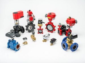
Today the use of motorized control valves in large and small hydronic heating and cooling systems is very common. As a primer on their function and use, this article will explore available valve options, types of actuators and application examples without going into too many details about the control algorithm or strategies.
Motorized control valves in small hydronic heating and cooling systems is very common.
COMMON TYPES OF ACTUATORS
On/Off : 24Vac, 110Vac motor actuators can come in one of two ways. They are either power open and power close, or power one way (open or close) and spring return the other. Unlike the floating action type motors, these actuators do not have anything in between. They truly are either open or closed and are typically used on flow control valves that allow or stop the flow of fluid in the system, such as zone control valves, shut off/isolation valves or diverting valves.
Floating Action: 24Vac, 110Vac or 230Vac valve motor actuators receive a powered voltage control signal in order to move the valve. Without power applied to the motor, the valve will remain in the position it was in at the time the power was removed. Power is required at all times to actuate the valve one way or another. These valves and motors are typically used in applications where the control of a fluid temperature is desired, or the amount of flow (GPM) in the connected system piping must be controlled. Applications include outdoor reset or setpoint fluid temperature in the distribution piping or variable flow through a distribution loop or riser based on temperature differential (deltaT) or pressure differential (deltaP) for hydronic heating and cooling systems. Floating action type control valves are slow responding and provide a very cost effective way to gain control in those scenarios. Typically, Modulating: 0-10Vdc (2-10Vdc) Or 0-20mA (4-20mA) valve motor actuators are powered all of the time. A voltage in direct current (Vdc – polarity sensitive) or a small current in Milliamp (mA) signal is provided to the valve’s actuating motor to move the valve’s position. The max value (10Vdc or 20mA) usually represents full output and the minimum value (0 or 2Vdc and 0 or 4mA) represents the minimum output. Most control systems would allow for additional output limits to be programmed into its algorithm to allow for fine-tuning of the valve’s output.
Without the control signal, the valve motor would typically return the valve to the starting position (off). These kind of valves and motors are generally used in applications where the control of a fluid water temperature or the amount of flow (GPM) in the connected system piping is desired. Modulating control valves typically respond faster than that of floating action type valves.
Control Valve Applications
A two-way control valve is most often used for on/off zone/flow control. However, two-way control valves with characterized design can be used for modulating purposes also. Many readers will be familiar with using two-way control valves for zone/flow control purposes, so let’s look at an example of a piping option using a two-way characterized valve for fluid temperature control purposes in Figure 1.
Figure 1
Figure 2 Two-way modulating control valves used for a variable flow application
In the example shown in Figure 1, a two-way characterized control valve is matched with a modulating actuating motor (0-10Vdc or 0-20mA) and controlled by a control system based on the fluid temperature requirement on the system loop. A balancing or globe valve is installed on the system side in between the two injection Tee’s. This creates a pressure differential that can be made up through the modulating control valve and to ensure flow through the mixing device.
Alternatively, Figure 2 shows two-way modulating control valves used for a variable flow application. In this example a deltaT controller could provide the modulating signal to the valve based on the deltaT across each the distribution loop to accommodate load balancing where there are multiple distribution loops. This will help maximize the building’s operating efficiencies.
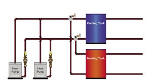
Figure 3a Three-way diverting control valves-diverting to one of two loads
Figure 3b Three-way diverting control valves diverting to one load alternatively
Three-way control valves can be used for on/off, floating action and modulating applications. Three-ways are often the most versatile of valves and, depending on the installation practice, can be used in any which way needed. Here are some application examples.
Figures 3a and b show a three-way control valve in the on/off diverting
application. Figure 3a shows a source diverting to one of two loads and Figure 3b shows two sources diverting to one load alternatively. These applications generally would take advantage of on/off motorized valve actuators (with spring return to the default position). Modulating valves may also be used for this application and the control strategy adapted to only produce a fully open (max. output) or fully closed (min. output) signal to the motor.
Figure 4 Three-way characterized control valve
Figure 4 shows the application of the three-way control valve for either floating action or modulating valve motor actuators used in a fluid temperature mixing requirement. Note the proper isolation of the mixing and system loop from the primary loop through some sort of hydraulic separation. Hydraulic separation can come in the form of closely spaced tees on the primary loop as shown, or through a manufactured hydraulic separator.
Figure 5 Three-way characterized control valve
Figure 5 shows the use of the three-way control valve for variable flow control using either the modulating or floating action motorized actuator operated by a control that may control discharge air temperature downstream of the heating coil in this fan coil or make-up air unit.
In Figure 6, a four-way control valve with a floating action or modulating motor actuator is used to control the fluid supply temperature in a snowmelt system based on slab and system requirements. This example shows the mixing valve on the system side, isolated by a heat exchanger from the primary heating distribution piping system.
Figure 6 Four-way control valve
Alternatively, if used for mixing, a four-way mixing valve could be piped just like the three-way valve was shown in Figure 4, where it is hydraulically separated from the primary heating or cooling loop by either a primary/secondary arrangement using a set of closely spaced tees, or the addition of a manufactured hydraulic separator.
Figure 7 More complex hydronic system
The system in Figure 7 showcases a condensing boiler; an indirect domestic hot water tank; a make-up air unit; several fan coils over two floors and separate distribution piping loops for each; a single zone of snowmelt; and two mixed fluid temperature loops for radiant floor heating zones.
This is not to suggest that one should use all kinds of different type of valves and control strategies on a job, but it does highlight the versatility of hydronic heating and cooling systems and the number of options available. The next step to optimizing those options in your system designs is to understand control logic and algorithm – these topics will be explored in an upcoming issue.
Mike Miller is chair of the Canadian Hydronics Council (CHC) and director of sales, building services with Taco Canada Ltd. He can be reached at hydronicsmike@taco-hvac.com.

