
Stemming The Flow
March 1, 2013 | By John Siegenthaler
Balancing a recirculating domestic hot water system.
An annoying characteristic of many plumbing systems is when a person opens a hot water tap, but has to wait several seconds for warm water to flow from that tap. This happens because there has not been a draw of hot water for some time and the water left in the piping from the previous draw has cooled off.
The U.S. Department of Energy estimates that an average family of four wastes up to 14 000 gallons of water annually, simply by opening taps, and waiting for hot water to arrive. This obviously increases water and sewer bills, adds to sewage treatment streams and wastes energy. In warmer months, the heat lost from hot water piping also adds to the building’s cooling load.
One of the solutions to this situation is to create a recirculating domestic hot water system. The basic idea is simple, and illustrated in Figure 1.
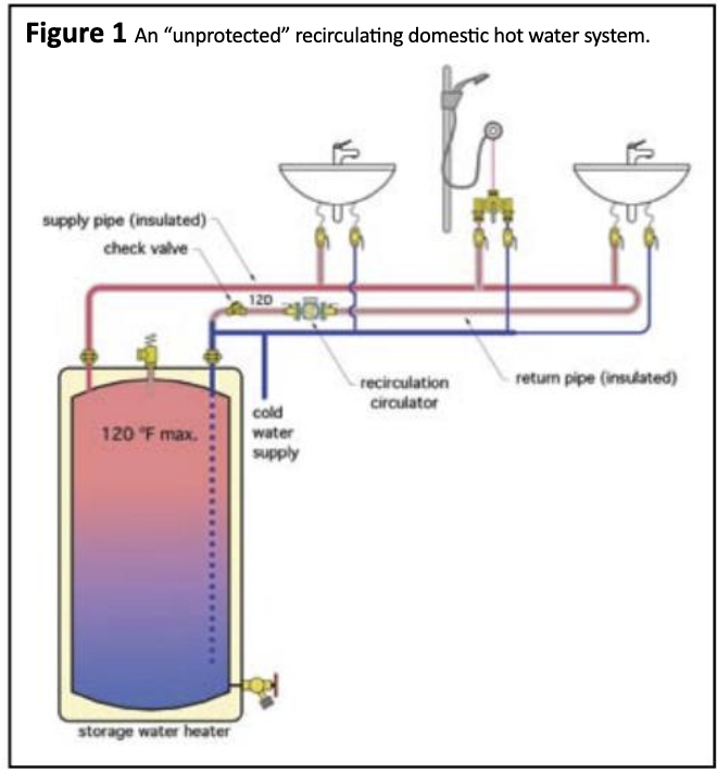
Figure 1
In this system, hot water, presumably at maximum temperature no higher than 120F, flows from the storage water heater through the building’s hot water supply piping. After the hot water supply pipe tees off to the last fixture, it connects to a smaller diameter return pipe that goes back to the storage tank. A small bronze or stainless steel circulator creates just enough flow keep the temperature drop along the hot water supply main to perhaps 2F to 4F. Each fixture is now within a few feet of piping that has hot water in it, at least when hot water service is deemed necessary. In some buildings, recirculating hot water is available 24 hours per day, and seven days per week. In other buildings, hot water recirculation is controlled by a timer or other controller. Turning off the recirculation system at night saves energy. If someone has to have hot water at 3:00 a.m., they may either open the tap and wait for it, or in some systems, press a button that immediately starts the recirculation circulator and operates it for a short override period.
A check valve is installed downstream of the recirculation circulator. Its purpose is to prevent any cold water from being drawn backward through the recirculation pipe, and eventually to a hot water tap, if the recirculation circulator is not operating.
To minimize heat loss, it is crucial that the hot water supply pipe, the return pipe and the hot water risers to each fixture are insulated. Without code provisions that require otherwise, I suggest a minimum of ½-inch thick foam rubber insulation, or equivalent on all hot water piping.
DO NOT GO UNPROTECTED
Although the system in Figure 1 is functional, it lacks the safety associated with either a single point-of-distribution (POD) thermostatic mixing valve near the water heater, or multiple point-of-use (POU) thermostatic mixing valves at each fixture. Without one of these means of protection, the temperature of water arriving at the fixtures will be essentially the same as the temperature at the top of the water heater.
If the tank’s thermostat is set above 120F, or its temperature controller is inaccurate, or the tank is heated by some non-thermostatically limited heat source, such as solar collectors, the water arriving at the fixture could quickly scald someone. Such a situation can cause life-changing harm to an unsuspecting building occupant. I have a policy that no drawings or specifications involving domestic water heating ever leave our office without properly selected thermostatic mixing valves to protect against scalding. I am continually amazed at how many commercial properties have scalding hot water readily available at the taps. These situations are just lawsuits waiting to happen.
Figure 2 shows how the system from Figure 1 can be modified to include a POU thermostatic mixing valve at each lavatory. The shower valve has its own integral anti-scald protection mechanism.
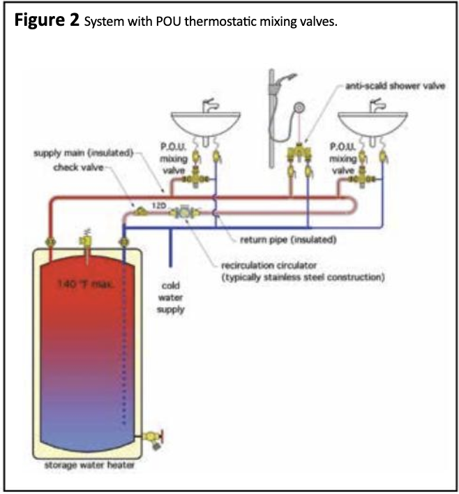
Figure 2
This configuration allows the water temperature leaving the hot water source to be above 120F, such as may be necessary to kill Legionella bacteria. It also allows lower, individually set delivery temperatures at each fixture.
RECIRCULATION WITH POD MIXING VALVES
So how can one design a domestic hot water delivery system that incorporates both recirculation, and protection from scalding? One common attempt at such a system is shown in Figure 3.
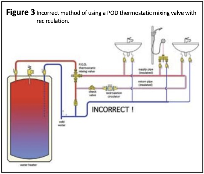
Figure 3
The mistake is to just tee the return side of the recirculating loop to the cold water pipe supplying the thermostatic mixing valve. Over time, this piping causes the cold port of the mixing valve to approach fully open, while the hot port approaches fully closed. Under this condition, there will be very little if any transfer of hot water from the water heater to the recirculating loop. This causes the temperature in the recirculating loop to drop, often well below the desired set point.
The correct method for incorporating a POD thermostatic mixing valve with recirculation is shown in Figure 4. This system includes a bypass valve (1), and a return valve (2). The purpose of these valves is to regulate how much warm water, from the return side of the recirculating loop, flows back to the storage tank. When there is no hot water draw at the fixtures, the water flow rate back to the tank will be matched by an equal flow of hot water from the tank, into the recirculating loop. Ideally, this flow rate is adjusted so that the rate of heat transfer from the tank to the recirculating loop exactly balances the rate of heat loss from the recirculating loop. This allows the water temperature leaving the POD thermostatic mixing valve to remain stable.
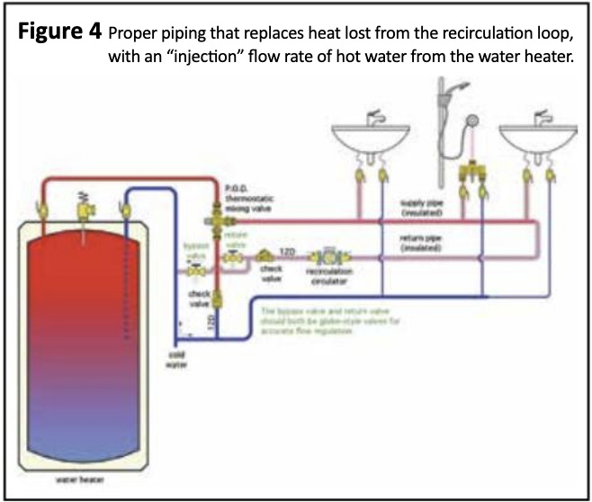
Figure 4
MAKING THE ADJUSTMENT
The bypass valve (1) and possibly the return valve (2) must be adjusted when there is no domestic water draw on the recirculating loop. Begin with the bypass valve (1) fully closed, and the return valve (2) fully open. Turn on the recirculating circulator, and let it run for several minutes. Under this condition the supply water temperature leaving the thermostatic mixing valve will likely be lower than the setting of the mixing valve.
Slowly open the bypass valve (1) and monitor the temperature leaving the thermostatic mixing valve. It will likely begin rising as some water returns to the tank, and an equal flow of hot water moves from the tank to the hot port of the mixing valve. When the temperature leaving the mixing valve remains stable, and is at, or very close to, the temperature setting of the thermostatic mixing valve, the bypass valve is correctly set.
The return valve (2) can remain fully open unless a situation occurs where the bypass valve (1) is fully open, but the temperature leaving the mixing valve is still too low. If this happens, partially close the return valve (2) to add flow resistance. This forces more flow through the bypass valve (1). Repeat the previously described procedure of slowly opening the bypass valve (1) until the water temperature leaving the mixing valve is stable.
The system should now provide a stable and safe supply water temperature to the hot water distribution piping. Hot water will be available to each fixture served by that piping within a second or two of opening a tap and thousands of gallons of otherwise wasted water will be saved every year. <>
John Siegenthaler, P.E., is a mechanical engineering graduate of Renssellaer Polytechnic Institute and a licensed professional engineer. www.hydronicpros.com
