
Piping layouts to avoid in hydronic systems
February 15, 2017 | By John Siegenthaler
Einstein’s definition of insanity was doing the same thing over and over and expecting different results. If that is true, there are some “insane” hydronic system designers in North America. They repeatedly cling to certain system piping configurations, even though existing projects using those configurations have produced problems.
One incorrect piping layout that I have seen repeated many times could be described as a “morphing” of primary/secondary piping, and a classic header-type multi-zone distribution system. I have seen it as installed hardware, and in neatly prepared CAD drawings created by professional engineers. The latest rendition of this problematic piping layout recently popped up in an e-mail sent to me for review.

Figure 1
The piping error that I am referring to is represented by Figure 1.
This piping layout is neither primary/secondary, nor a “header-type” multi-zone syste. It is undefined among proven hydronic piping designs.
My guess as to how this rogue piping layout repeatedly manifests itself is that the designer begins thinking about primary/secondary piping, and therefore thinks they needs a primary loop. The heat source(s) will inject heat into this loop, and the load circuits will extract heat from it.
Related: When to use a three-pipe buffer tank configuration
The designer proceeds to sketch out the loop, and puts in a primary loop circulator. Next it is time to add some load circuits. This is where the designer’s memory flashes back to neatly aligned zone circulators all lined up on a wall. With that in mind, the designer connects the supply side of each zone circuit to the upper part of the loop (thinking it is a header), and the return side to the lower portion of the loop (again viewing it as a header). The fact that the “headers” are connected at their ends doesn’t seem to matter.
WHAT’S WRONG?
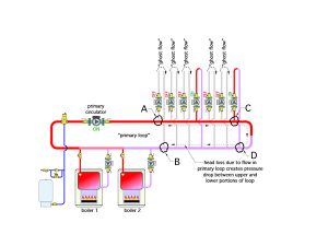
Figure 2
One problem with this design can be envisioned if you consider the pressures within the primary loop when only the primary loop circulator is operating. There is a pressure drop between the upper portion of the loop, where the supply side of the load circuits connect, and the lower portion of the loop, where the return side of the load circuits connect. This is illustrated in Figure 2.
If just the primary circulator was running, the pressure differential would be highest between points A and B due to the head loss along the longest loop path. It would decrease to some minimum value between points C and D. However, the pressure differential across any given load circuit at any given time will also be influenced by the on / off status of the load circulators, and thus highly variable. Still, it is possible that the pressure differential between points where a load circuit begins and ends could be several pounds per square inch (psi).
If the pressure at point A is higher than the pressure at point B, the water “wants” to move from A to B. And, if nothing blocks its path, the water will flow from A to B. The result is heat delivery into a circuit in which the zone circulator is off, and there is no need of heat. Call it heat migration, ghost flow, or whatever you want. It is not supposed to occur, and customers have every right to complain when it does.
It is conceivable that all the zone circuits could have some flow through them when only one zone is actually calling for heat. Flow would occur in any load circuit where the forward opening resistance of any check valve (which is typically 0.3-0.5 psi) is smaller than the developed pressure differential between the supply and return sides of that circuit.
The rate of undesirable heat migration depends on the pressure differential between the supply and return of each zone circuit, and the amount of recirculation mixing that occurs. The latter depends on the flow rate in the primary loop versus the flow rates in the load circuits. If flow is rocketing through the primary loop – because someone thinks the primary loop flow has to be at least equal to the sum of the load circuit flows (which is NOT true), then there won’t be recirculation mixing. However, if the flow in the primary loop is less than the sum of the active load circuit flow rates, there is sure to be recirculation somewhere. Think like water. Why should the water travel all the way back to where the boiler(s) are connected to the primary loop if it can just take a shorter detour and end up back at the inlet of a zone circulator?
If you are going to build a true primary/secondary system, each load circuit and each heat source needs to connect to the primary loop using a pair of closely spaced tees. These tees isolate the pressure dynamics of each circulator from the other circulators in the system. This is called hydraulic separation.
MORE PROBLEMS
The system shown in Figure 1 accurately represents a drawing that I received. Aside from the “morphed” piping layout, there are several other details that should be of concern:
- There are no check valves in the load circuits to prevent reverse flow when some loads are active while others are not.
- There are no purging valves in the load circuits.
- There is a swing check valve mounted in a vertical pipe coming from the boiler. Swing check valves should never be mounted in vertical piping. Under some conditions the flapper within the check valve can “hang” in the open position when flow stops, and slam shut when sufficient reverse flow develops. This can create a strong water hammer effect.
- The tees connecting the boilers to the “primary loop” should be as close together as possible. The pressure drop between the more widely separated tees connecting the boiler to the “primary loop” in Figure 1 will tend to induce some flow through an inactive boiler. This increases heat loss from the boiler jacket and creates convective air currents that such heat up the chimney.
LOSE THE LOOP
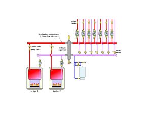
Figure 3
Properly designed primary/secondary systems work. Still, in my opinion, there are better options that provide the benefits of primary/secondary piping, but with simpler and less expensive piping configurations (as shown in Figure 3).
This system connects the boilers to a header system that leads to a hydraulic separator. The load circuits connect to short/generously sized headers leaving the right side of the hydraulic separator. High performance air and dirt separation is provided by the coalescing media inside the hydraulic separator. This eliminates the need for air and dirt separators as individual components.
Related: Make the right choice: An overview of new plumbing and hydronic valves
By keeping the headers short and generously sized, the pressure drop along the header is very low. This in combination with the very low pressure drop through the hydraulic separator provides good hydraulic separation of all the circulators in the system.
My suggestion is to size the headers so that the flow velocity within them does not exceed two feet per second when carrying their maximum flow rate.
This piping layout eliminates the “ghost flow” and possible recirculation issues previously described. It also provides equal supply temperatures to each of the load circuits. It does away with the primary loop circulator, and perhaps most importantly, it eliminates the operating cost of a primary loop circulator over the life of the system. The savings associated with the latter could easily add up to more than the cost of the hydraulic separator.
So please, do not repeatedly prove that Einstein was right about insanity. If you are intent on building a primary/secondary system be sure you construct it with closely spaced tees and a properly sized primary circulator. Consider using a hydraulic separator to achieve the benefits of a primary/secondary system with simpler piping and lower life cycle operating cost.
 John Siegenthaler, P.E., is a mechanical engineering graduate of Rensselaer Polytechnic Institute and a licensed professional engineer. He has over 34 years experience in designing modern hydronic heating systems. Siegenthaler’s latest book, Heating with Renewable Energy, was released recently (see www.hydronicpros.com for more information).

