
Simple and sophisticated hydronic systems
March 21, 2017 | By John Siegenthaler
As the North American hydronics industry has grown, so has the complexity of its systems. Many installations that are now featured as award winning examples of hydronic heating contain thousands of parts and pieces. They can be so complex that only the person who designed and installed them understands how they operate, or can fix them when they do not. That is not good for the system owner or for the industry.
Although there are some buildings, perhaps even some single family homes that benefit from having a dozen or more heating zones, as well as a wide mixture of heat emitters, they do not represent the mass market in which hydronics still only holds a single-digit share. Promoting the concept of hydronic heating with photos of elaborate systems containing lots of hardware can easily send the wrong marketing message. Instead of comfort combined with peace-of-mind reliability the average consumer may be thinking “expensive, complex and what happens when it breaks?”
CUTTING EDGE CONCEPTS
Instead of a wall full of circulators or zone valves, let’s look at a simple system that provides space heating and domestic hot water. It is simple in that only one type of heat emitter is used; simple because the control logic is pre-engineered rather than customized; and simple from a piping layout standpoint.
Perhaps you are thinking that simple excludes being state of the art. This is not the case. The system discussed here uses cutting edge concepts such as outdoor reset control, boiler modulation and variable speed pumping. It personifies the state of the art in hydronics technology but with far fewer parts and pieces. A piping schematic of the system is shown in Figure 1.
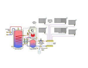
Figure 1 Piping schematic for simple system
We will examine each subsystem independently and then look at how they all work together.
HEAT SOURCE
The system’s only heat source is a mod/con boiler. A wide assortment of such boilers is available in North America, and most are capable of operating with either natural gas or propane. All have internal control logic that allows them to regulate the water temperature supplied to the heat emitters in response to outdoor temperature (e.g. outdoor reset control). The warmer it is outside the lower the boiler temperature and the higher its efficiency. These “partial load” conditions represent the majority of the heating season. The system must be stable and efficient during these times, as well as under brief peak load conditions.
When it is time for domestic water heating a mod/con boiler temporarily ignores outdoor temperature and fires itself to an elevated “setpoint” temperature to drive all heat output through the heat exchanger in the indirect water heater. During this mode of operation circulator (P2) is turned off while circulator (P1) operates.
BUFFER TANK
This system provides room-by-room comfort control using individually controlled panel radiators. Each radiator represents a separate zone. There will often be times when the heating load (perhaps a single room) is far lower than the minimum heat output rate of the boiler. Under such circumstances any low mass boiler with minimal water content will short cycle. This can lead to premature failure of ignition and combustion components.
Short cycling is avoided by installing a well-insulated buffer tank in the system to provide additional thermal mass between heat production and heat release. The boiler maintains the temperature of the buffer tank based on outdoor reset control. This happens whenever the system is not in “warm weather shut down” mode, regardless of what the space heating demand happens to be. Thus, a small heat emitter such as a bathroom towel warmer could operate at a “trickle” rate of heat transfer without forcing the boiler to operate until the buffer tank temperature drops below the required lower limit. Whenever space heating may be needed there’s always warm water in the buffer tank ready to immediately meet the demand. A 25-gallon buffer tank would provide 44 per cent more thermal mass than a 400-pound cast-iron boiler with a 12-gallon water volume. With a reasonable temperature cycling range of 15F to 20F it provides very adequate thermal mass and can often be mounted directly below the wall-hung mod/con boiler as shown in Figure 1.
The buffer tank also hydraulically separates the pressure dynamics of the boiler circulator (P2) from those of the variable speed distribution circulator (P3). It provides a low flow velocity zone allowing air bubbles to rise to where they can be captured and expelled through an automatic float-type vent.
PANEL RADS
This system uses fluted steel panel radiators for all heat emitters. These panels offer several benefits:
They are adaptable to different interiors. They come in a variety of heights, widths, and depths that allow them to fit into a wide variety of situations.
They are one of the easiest heat emitters to install in new homes as well as retrofit applications. They are relatively light and can be supported by almost any wall.
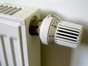
Figure 2 Non electric thermostatic radiator valves
They lend themselves to room-by-room zoning using non-electric thermostatic radiator valves, as shown in Figure 2, providing fully modulating room-by-room comfort control without a mile of thermostat wires. This is a tremendous benefit relative to the complexities and installation time associated with wire-based thermostats in every room.
Panel radiators have very low thermal mass and thus respond quickly to changing internal heat gain situations. In short, they warm up and cool down much faster than heated floors. This is especially desirable in buildings with significant internal heat gain potential.
With proper sizing, panel radiators can operate at relatively low water temperatures and thus enable the mod/con boiler to operate in a condensing mode, even under design load conditions. I suggest sizing panel radiators for design load output with a supply water temperature of 120F. Operating panels at relatively low water temperatures also increases the ratio of radiant to convective heat output, which further enhances comfort.
Each panel radiator is equipped with a dual isolating valve enabling it to be totally isolated from the remainder of the system if it ever has to be removed.
DISTRIBUTION PIPING
Each panel radiator is supplied by a homerun distribution circuit, which is connected to a common manifold station. These homerun circuits can be 1⁄2″ PEX or PEX-AL-PEX tubing. Some of the homerun piping segments could even come from “remnant” coils of tubing left over from radiant panel installations.
Because the panel radiators each have their own balancing valve, as well as dual isolating valves at the supply and return connections, it is not necessary to use a manifold station equipped with such valves. A simple copper manifold such as the one shown in Figure 3 is fine.
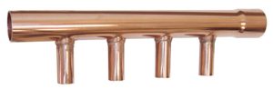
Figure 3 Valveless copper manifold
The homerun distribution system provides several advan-
tages:
The small diameter flexible tubing can be routed through the framing cavities of the building much like electrical cable. The ability to “fish” tubing through closed framing cavities is a tremendous advantage over rigid tubing, especially in retrofit situations.
Homerun systems deliver the same water temperature to each heat emitter. This simplifies sizing since the temperature drop associated with series type circuits is not present. It also allows each heat emitter to take equal advantage of outdoor reset control.
In combination with thermostatic valves at each panel radiator, homerun systems allow the temperature of each room to be individually controlled. The master bedroom can be kept cool for sleeping while the master bathroom remains toasty warm for a morning shower. Unoccupied rooms can be set at lower temperatures to conserve fuel.
CRUISE CONTROL
Another piece of the performance pie is a variable speed pressure regulated circulator. These are now widely available in North America. Two examples are shown in Figure 4.
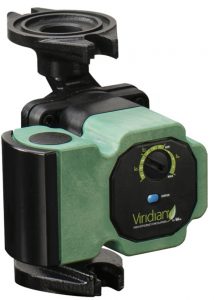
Figure 4 Variable speed pressure regulated circulators
In this type of system the circulator should be set to maintain a constant differential pressure. As the thermostatic valves on the panel rads open and close, the circulator senses the “attempt” to change differential pressure and responds with a motor speed adjustment that keeps the pressure constant. This keeps the flow through the active zone circuit stable regardless of what other zones happen to be on, off or at some intermediate flow rate. Think of it as “cruise control” for differential 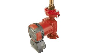 pressure. It is just the right amount of pumping effort under all conditions.
These circulators also operate on a fraction of the electrical energy required by a typical fixed speed circulator with a permanent split capacitor motor. Imagine an entire heating distribution system, in a typical North American house, operating on less than 45 watts of pumping power on the coldest day of the year. It is possible with this technology.
SUM OF THE PARTS
Although simple in concept this system can deliver excellent comfort on a room-by-room basis while operating at very high thermal efficiency and low electrical power consumption. It is one of the easiest distribution systems to install in new and retrofit situations. There are no controllers other than those already built into the mod/con boiler and the circulator. Wiring consists of supplying power to the boiler and three circulators. No room thermostats, transformers, or zone relay panels are required. Domestic water heating is handled as a prioritized load allowing for the fastest possible recovery of tank temperature.
If you feel the systems you are presently installing are getting a bit complex, consider giving this concept a try. It will quickly convince you that hydronic systems do not have to be complex to be state of the art.
John Siegenthaler, P.E., is a mechanical engineering graduate of Rensselaer Polytechnic Institute and a licensed professional engineer. He has over 34 years experience in designing modern hydronic heating systems. Siegenthaler’s latest book, Heating with Renewable Energy, was released recently (see www.hydronicpros.com for more information).
