
Strive for perfection in hydronic system design
October 28, 2017 | By John Siegenthaler

Figure 1 The pressure drop within the copper basketball header would be very low, but not quite zero. If this header were well insulated it could also provide very low (but not zero) heat loss.
We live in a world where, for the most part, theoretical ideals can only be approached rather than fully realized. For example, imagine a building with heat loss characteristics such that the rate of heat loss always matched the rate of internal heat generation from sunlight, people, and equipment. Such a building would not require any heating system. If all buildings could achieve this condition there would be no need of the H in HVAC.
Even though most theoretical ideals cannot be fully achieved, it is helpful to think about them, and drive our designs toward them. Such an approach encourages the industry to strive for continuous improvement, higher efficiencies, improved reliability, and smoother system operation.
Let’s take a look at several theoretical ideals, as well as design practices that move the systems we create toward them.
ZERO ∆T
Let’s start with heat exchangers. The ideal heat exchanger would have enough internal surface area to create a condition where the temperature of the heated fluid leaving the heat exchanger is exactly the same as the temperature of the entering heating fluid.
For example, imagine an antifreeze solution coming from a solar collector at 140F. It enters a heat exchanger and transfers heat to a stream of water. The water leaves this ideal heat exchanger at 140F. Not 139.9F, but 140F. Such a heat exchanger would have a 0F approach temperature difference (e.g., the difference in temperature between the entering heating fluid, and the existing heated fluid).
All heat that could possibly be transferred from the antifreeze solution to the water would do so in this scenario. The bad news is that this would require a heat exchanger with infinite internal surface area and that is going to be really expensive!
Fortunately, it is now relatively easy to select heat exchangers using online software provided by heat exchanger manufacturers. Heat exchangers with approach temperature differences of 5F or less can be selected based on known flow rates and entering fluid temperatures. The smaller the approach temperature difference between the incoming heating fluid and leaving heated fluid, the larger the heat exchanger has to be, and bigger heat exchangers cost more. When selecting heat exchangers, designers should evaluate performance gains versus higher cost over the full life cycle of the system. It often makes sense to go with a larger exchanger where the incrementally better performance results in the useful capture of millions, or even billions, of Btus over many years of operation.
By the way, an ideal heat exchanger would also have to operate with zero pressure drop on both sides, and remain free of any scaling or other fouling conditions that could degrade its thermal performance. Designers should approach these ideals by selecting heat exchangers for minimal pressure drop, and operate them with proper ancillary details such as demineralized water and devices that provide effective upstream dirt separation.
SHORT / FAT HEADERS
Here is a question that probably has not kept you awake at night: What is an ideal hydronic header? The answer is pretty simple: One that splits up the entering flow into the necessary branches while producing zero pressure drop and zero heat loss.
Imagine a “copper basketball” with tubing supplying several branch circuits sticking out of it in several directions. A single larger tube carries heated water into the copper basketball header. The concept is shown two-dimensionally, in Figure 1.
The pressure drop within the copper basketball header would be very low, but not quite zero. If this header were well insulated it could also provide very low (but not zero) heat loss.
Now, imagine how difficult it would be to install such a header in a typical mechanical room. Think about what it would cost to manufacturer and ship such a header to a job site. Although its hydraulic and thermal performance would be very good, this concept does not pass the practicality test.
The next best thing that would pass the practicality test is a “short/fat” header; one that minimizes rather than eliminates pressure drop and one that arranges the branch circuit connections in a row or two to make them compatible with typical piping layouts. The concept is shown in Figure 2.
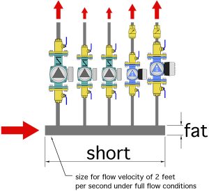
Figure 2
How do you create a short fat header? My suggestion is to select a pipe size that yields a flow velocity of only two feet per second at the entrance of the header when all branch circuits are operating at full flow rate.
Selecting the header size based on this criterion might earn you some weird looks from installers who are less concerned about approaching ideal conditions, or more concerned about tradition. But be assured that you are providing a detail that conserves pumping power and even helps contribute to good hydraulic separation of multiple circulators supplied from that header.
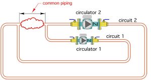
Figure 3
COMPLETE SEPARATION
Speaking of hydraulic separation, it is a desirable trait in any hydronic system having multiple circulators that can operate at the same time. It is also a pretty straightforward concept that we have discussed in several previous HPAC articles.
Good hydraulic separation (see Figure 3) is achieved by keeping the pressure drop in “common piping” that is shared by two or more circuits, each having its own circulator, as low as possible. The common piping could be a pipe, a tank, a heat source, a pair of closely spaced tees, a collection of piping components, or, not surprisingly, a device called a hydraulic separator.
Perfect hydraulic separation would require zero pressure drop though the common piping, with all circulators running. It is impossible to create such perfections. Fortunately, when it comes to hydraulic separation, almost perfect is good enough. Just identify the component(s) that will be included in the common piping and make selections that keep the pressure drop through this portion of the system as low as possible. A ballpark estimate is to keep the pressure drop through the common piping to less than one per cent of that along any circuit connected to the common piping.
“TREAT YOUR HEAT LIKE YOUR LIGHTS…”
The suggestion that heat be treated like our lights was offered by Richard Watson at a Radiant Panel Association conference held many years ago. He was describing the ability of very low thermal mass “ENERJOY” electric radiant panels, manufactured by Solid State Heating Corporation, to begin releasing radiant heat almost the same moment they were supplied with electricity, just like most light bulbs emit light the moment they are energized.
It is a simple but profound concept. One that arguably favours a very low thermal mass electrically heated panel versus a typical current-generation hydronic radiant panel.
Imagine not having to maintain each room in a building at a normal comfort temperature just so you could be instantly comfortable if you happened to enter that room. If an instant output radiant panel could be created, the room could be maintained at a lower temperature when unoccupied, with comfort instantly restored when someone entered that room. This would reduce its rate of heat loss, and thus reduce the seasonal heating energy use.
A hypothetical hydronic heat emitter with zero thermal mass could begin emitting radiant and convective heat the moment heated water passed into it. Such a panel could adjust its heat output to moment-by-moment changes in internal heat gains from sunlight, people and equipment. It would store very little heat when it is time to put the space it heats into temperature setback. When the setback period ended, comfort could be instantly restored.
Again, we may never see a hydronic radiant with zero thermal mass, but there are currently available panel radiators that have less than one per cent of the thermal mass of a four-inch thick, heated concrete floor slab. They contain minimal amounts of water and metal relative to their heat emitting potential. Such panels can thermally accelerate and decelerate very quickly to compensate for changes in internal heat gains. They are an excellent choice in modern highly insulated buildings that are subject to variable internal heat gains.
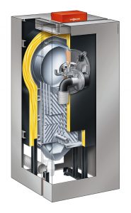
Courtesy Viessmann
BOILER PERFECTION
There are hundreds, perhaps even thousands, of different boilers now available for hydronic systems. They range from traditional high thermal mass cast-iron sectional designs, to those with compact stainless steel heat exchangers that hold less than one gallon of water.
So, which end of this boiler spectrum is ideal? The answer is neither.
In my opinion, the ideal hydronic boiler would have a zero thermal mass combustion system combined with a thermally isolated volume of water that could eliminate the need of a separate buffer tank. This
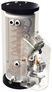
Courtesy HTP
combination would also have zero pressure drop and zero rate of heat loss to its surroundings.
About now you are probably thinking that imaging such a boiler is a waste of time. But instead of dismissing what is arguably impossible, think instead about approaching these ideal characteristics.
It certainly is possible to build a device that holds several gallons of water in a very well insulated enclosure. It is also possible to build a combustion assembly/heat exchanger that has relatively low mass. Put them together into a marketable product and you will be close to that theoretical ideal. Such products do exist in both Europe and North America. Figures 4 and 5 show a couple of examples.
INSTANT SOLAR
A few years ago we installed a grid-connect solar photovoltaic system at our house. I am inspired by how rapidly the output wattage of this array changes as the array goes into and out of shading by a cloud. For all practical purposes the array responds instantly to changing solar radiation conditions.
This is not the case with solar thermal collectors. There are definitely times when a solar thermal system fails to turn on to grab what might only be a few seconds worth of available solar radiation shining down between passing clouds.
This happens because the collector’s metal absorber plate, and any fluid it contains, represents thermal mass that cannot be sufficiently warmed by a few seconds of solar radiation, at least to the point of activating a differential temperature controller.
But what if it could? What if someone created a solar thermal collector with an absorber plate having an extremely small thermal mass? Perhaps it would be built using carbon nanotubes, or some other synthetic material that hasn’t yet migrated from the laboratory to the production line. What if the enclosure around that absorber plate approached zero heat loss, and the glazing above the absorbed plate approached a perfect transmissivity of 1.00?
Such a collector could grab short bursts of solar radiation and instantly transfer it to a fluid stream.
As with the perfect boiler, the ideal solar thermal collector cannot be built, at least not with the materials and technology currently available. However, the concept should give us pause to consider how changes to current collector designs might provide benefits. For example, could we build a collector absorber plate with less material, or with far less internal fluid volume? If we could, that collector’s ability to capture short pulses of solar radiation between passing clouds would improve. A better-insulated enclosure would complement such an absorber.
DREAM ON
Imagine if no one thought that the Wright Brothers’ first airplane could be improved upon, or if it would be impossible to have a computer on a desktop much less on our wrist? What if no one in the early 1900s had envisioned an electrically-powered circulator to move water through a hot water heating system, or had totally dismissed the future of hydronic radiant heating because some systems using metal piping embedded in concrete had sprung leaks?
The quest to achieving the ideal starts by conceptualizing it and moving toward it, often in small steps. It is my hope that future practitioners of hydronic heating and cooling will look back on what we do today as, acceptable for the time, but far from the state of the art at that future time. Continue to strive for the ideals.

John Siegenthaler
John Siegenthaler, P.E., is a mechanical engineering graduate of Rensselaer Polytechnic Institute and a licensed professional engineer. He has over 34 years experience in designing modern hydronic heating systems. Siegenthaler’s latest book, Heating with Renewable Energy, was released recently (see www.hydronicpros.com for more information).
