
10 details for expansion tanks
September 1, 2020 | By John Siegenthaler, PE
There are several design and installation details that should be used to properly incorporate an expansion tank into a closed-loop hydronic system.
Water in its liquid state, like nearly all physical materials, increases in volume when heated and decreases when cooled. These actions occur at a molecular level. Although it may appear that more water is being “created” as a given volume of water gets heated, that’s not the case. The same number of molecules are present, they’re just taking up more space.
Since water molecules are very small, one might assume that thermal expansion is a “weak” effect. However, that assumption is very wrong. Any attempt to constrain molecular expansion will be met by tremendous forces. If a strong metal container—such as a hydronic piping system—were to be completely filled with liquid water, sealed from the atmosphere, and heated, it would experience a rapid increase in pressure. If allowed to increase by further heating, the container would eventually burst, in some cases violently. That’s why all closed-loop hydronic systems must have a pressure relief valve.
Since we can’t mechanically “overpower” the expansion of water, we have to accommodate it. We need to give it something to “push” against when heated.
That something is a predetermined volume of air that stays within a closed hydronic system. The container for that air is called an expansion tank.
As the system’s water expands it pushes against the air in the tank causing it to compress. When the water cools and contracts, the air re-expands.
Today, the most commonly-used expansion tanks use a highly flexible butyl rubber or EPDM diaphragm to completely separate the air and water inside the tank. This diaphragm conforms to the internal surface of the tank when the air side is pressurized (Figure 1).
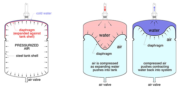
Figure 1
When the system’s water is heated, the increased volume moves into the tank. The diaphragm moves toward the captive air chamber. The air pressure in the tank increases as does the water pressure in the system. However, if the tank is properly sized, the increase is small and not enough to cause the pressure relief valve to open.
Diaphragm expansion tanks can be sized using charts or software. A detailed procedure for sizing diaphragm-type expansion tanks is given in reference 1 at the end of this article.
Details Matter
There are several design and installation details that should be used to properly incorporate an expansion tank into a closed-loop hydronic system.
Detail 1: Always make sure the expansion tank connects to the system close to the inlet side of the system’s circulator. This concept was correctly applied decades ago, but then slowly faded from practice as other installation “conveniences” seem to take priority.
The lack of attention to this detail is frequently the cause of chronic air entry into hydronic systems. Experienced hydronic technicians asked to fix systems that require frequent air purging know to check the placement of the expansion tank relative to the circulator inlet as one of the likely causes of the problem.
I’ve known of systems that suffered, from chronic air problems, but were instantly “cured” by repositioning the connection point of the expansion tank near the inlet of the circulator.
The point where the expansion tank connects to the piping system is the only location within the system where the pressure doesn’t change when the circulator is operating. This allows the differential pressure created by the circulator to be added to the static pressure in the system. Increased system pressure helps protect the circulator from cavitation and often allows for quieter operation. It also enhances the ability of air vents to eject air from the system. Figure 2 (below) shows acceptable placements of the tank.
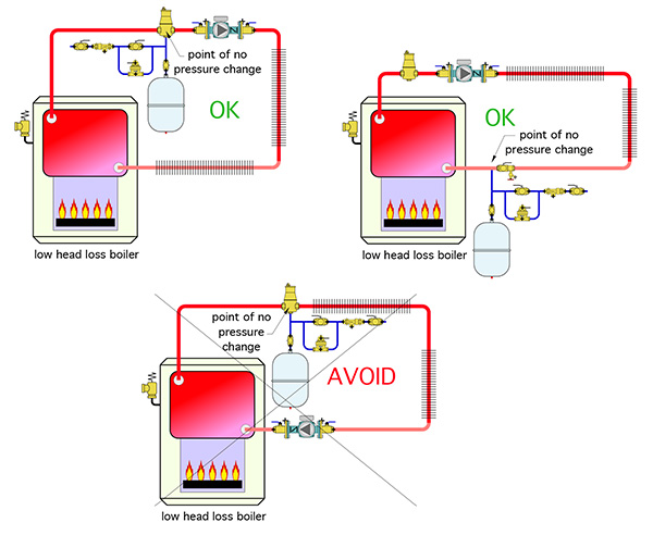
Figure 2
Detail 2: It’s always best to install diaphragm type expansion tanks vertically with the piping connection at the top. This reduces stress on the tank’s connection relative to horizontal mounting. It also prevents air in the piping from getting trapped on the water side of the expansion tank when the system is first filled. The latter can occur when the tank is mounted vertically, but with the connection at the bottom.
Detail 3: The life of an expansion tank depends on system operating temperature, pressure, fluid chemistry and oxygen content. The higher the operating temperature, and the higher the availability of dissolved oxygen in the system’s water, the shorter the expected life of the tank.
When a tank fails due to a ruptured diaphragm or corrosion it’s relatively easy to replace IF the installer provided an isolation valve between the tank and where it connects to the system. Without this valve you may have to drain gallons from the system just to unscrew the failed tank and screw in a new one.
I suggest a ball valve for isolating expansion tanks. After the system is first commissioned remove the handle from this valve and store it somewhere in the mechanical room. This reduces the chance that someone might inadvertently close the valve and thus isolate the tank from the system.
Detail 4: Consider oversizing the expansion tank. The typical tank sizing calculations determine the minimum tank volume. Using a larger tank, although likely more expensive, is fine. Doing so reduces changes in system pressure as the fluid temperature varies. In systems without automatic fluid make-up, such as a circuit operating on antifreeze, extra fluid in an oversized expansion tank helps keep a newly commissioned system operating at adequate pressures as the air separator removes dissolved air from the system.
Detail 5: Plan around the lowest temperature the fluid may achieve. In most hydronic heating systems expansion tank size and air side pressurization is based on the assumption that the cold fluid used to fill the system is in the temperature range of 45 to 60F.
That’s fine in most space heating applications. However, when an expansion tank is used in a solar collector circuit, or a snowmelting system, the antifreeze solution will at times be much colder, perhaps even below 0F. If the tank’s diaphragm is fully expanded against the steel shell at a fluid temperature of perhaps 45F, any further cooling of the fluid will likely cause negative pressure in the system, and possible inflow of air from a float-type vent. Reference 2 (at the end of this article) explains how to correct for this possibility. The concept is to add sufficient fluid to the tank during loop pressurization so the diaphragm is not completely expanded against the inside of the tank until all fluid in the system is at the lowest possible temperature.
Detail 6: Adjust for antifreeze. Solutions of propylene or ethylene glycol have higher coefficients of expansion compared to water. The higher the concentration of antifreeze the greater the expansion volume required. The increase in volume for water heated from 60 to 180F is about 3%. The increase in volume for a 50% solution of propylene glycol heated from 60 to 180F is about 4.5%. This higher expansion rate should be accounted for when sizing tanks for systems such as snowmelting, solar thermal or other applications where glycol-based antifreeze solutions are used.
Detail 7: Never use a standard expansion tank with a carbon steel shell in any type of open loop application, such as a system that uses potable water to carry heat to hydronic heat emitters (which is a bad idea for several other reasons). The elevated dissolved oxygen content of the water will accelerate corrosion of the carbon steel shell. This limitation also applies to closed-loop systems using non-barrier PEX tubing or other materials that may allow oxygen diffusion in the system. Expansion tanks with internal polymer linings should be used in any application where higher levels of dissolved oxygen could be present.
Detail 8: Don’t install expansion tanks directly below hydraulic separators. Doing so allows dirt collected at the bottom of the separator to drop into the expansion tank. Over time this could lead to failure of the diaphragm. If the tank needs to be near a hydraulic separator it’s best to mount it from a tee in either pipe connecting to the lower sidewall connections on the separator, as shown in Figure 3.
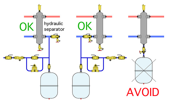
Figure 3
Detail 9: Whenever possible, avoid locating expansion tanks in proximity to very hot water. When the tank’s shell is heated the pressure of the air in the tank increases. This increases system pressure relative to a situation where the tank shell is cooler and may lead to leakage of the pressure relief valve.
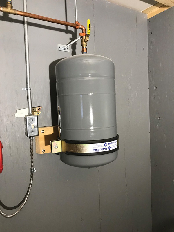
Figure 4
Detail 10: Don’t leave an expansion tank vulnerable to impact. Small expansion tanks that hang from ½-in. top connections can be easily bent by accidental impact. Ask me how I know this…
If the tank must be mounted in a vulnerable location use a strapping system to secure the shell to a solid surface, as shown in Figure 4 (above).
Expansion tanks perform a simple but very necessary function. Follow these details to keep them functioning as intended. <>

