
Air conditioning system procedures
May 23, 2019 | By Ian McTeer
Evaluating the performance of a cooling system requires the use of accurate tools and techniques.

EnerGuide ratings are difficult to replicate in the field.
Many of you will be familiar with the proverb “the proof of the pudding is in the eating” meaning something can only be a success after it has been used or consumed to the satisfaction of all. Heating and cooling systems qualify as “pudding” because a successful installation means the consumer benefits from the advertised advantages; however, the proof part may not be so evident even though the consumer professes to be satisfied.
The task of evaluating the performance of any given cooling system requires the use of accurate tools and techniques to actually demonstrate efficiency numbers associated with any particular product in the field. The process of gathering relevant facts can become time consuming and is further complicated by jobsite frustrations such as tiny mechanical rooms, dirty equipment and uncooperative weather.
Let’s look at some important cooling system start-up procedures.
RATED COMBINATIONS ONLY
Everyone in the residential HVAC industry should know by now that original equipment manufacturers (OEMs) test and rate the efficiency of all their products and further group them into acceptable equipment combinations. Outdoor units are tested and rated with various indoor evaporator coils, air handlers, oil furnaces and gas furnaces (including third party products) in accordance with standards acceptable to the Air Conditioning, Heating and Refrigeration Institute (AHRI).
OEMs certify equipment combinations in their own labs while AHRI conducts random spot tests to ensure the manufacturer is in compliance with the standards. Approved combinations are issued an AHRI Certified Reference Number; anyone can search the certified database at ahridirectoly.org.
AHRI certified ratings have been around for at least a decade thus any new cooling system startup should have certified components. Of course, older, pre-AHRI certification systems will also be starting up as cooling season progresses, leaving the HVAC technician to rely on tried, tested and true techniques that always apply to all systems.
AHRI ratings are an excellent guideline for predicting superior HVAC performance, but they do not always tell the full story. Take automotive fuel consumption ratings, for example.
The EnerGuide rating for my SUV approved by Transport Canada suggests the vehicle should consume 8.7 litres of fuel to travel 100 kilometers. This has never happened. On a good day I use 10 litres/100km on the highway. I will never be able to simulate Transport Canada test conditions under my actual conditions.
I said OEMs develop the Seasonal Energy Efficiency Ratio (SEER) and Energy Efficieny Ratio (EER) numbers in their own labs and based on the test standards meeting AHRI criteria. I fully believe any given manufacturer’s claim about a particular product delivering the numbers under laboratory conditions. Just like my vehicle’s fuel consumption claim, the AHRI certified values may not be easily achieved in the field.
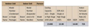
Figure 1 AHRI rating for a two-ton unit
Take this AHRI rating in Figure 1 for a two-ton outdoor unit connected to a variable speed indoor air handler as an example. I have removed the manufacturer name and unit model numbers.
For its day, 10 years ago, the system in Figure 1 made an impressive 16 SEER and 13 EER. Notice, however, the high efficiency rating is derived from a full-load air volume rate of 725 cfm (362.5 cfm/ton); cooling capacity is 21,400 Btuh. Obviously, if a building requires 23,500 Btuh at 400 cfm/ton, this is not the proper combination for that job.
If you install equipment in the wrong application or put it to work in a second-rate air handling system, you are just lead-footing down the HVAC road next to my SUV.
An equipment manufacturer may provide a variable speed air handler or gas furnace blower chart for a two-ton cooling system tabulated something like Figure 2.
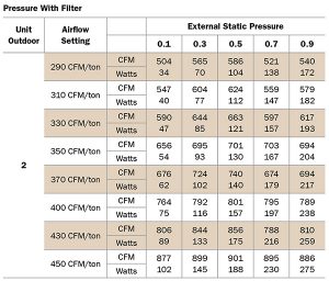
Figure 2 Blower chart
Installers and technicians should be trained to set-up variable speed blowers based on the AHRI certified airflow. This motor has settings for eight different airflow volumes to accommodate various types of AHRI rated equipment combinations. As the cfm/ton increases, motor watts increase. As the external static pressure moves beyond the rated value of 0.5 in. w.c. for this air handler, cfm decreases, motor watts increase and the rated efficiency goes down. Thus, the first step in a new residential HVAC system start-up is to make sure the system components are AHRI rated and set-up to work with each other.
AHRI rated systems must not have been used to provide temporary heat for houses under construction. This practice forces equipment, which is meant for comfort conditioning only to undergo the rigors of construction including exposure to dust, dirt, harsh chemicals and low temperature rise resulting in ruinous damage.
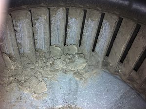
Centrifugal blower wheel had not been cleaned for years.
Such systems cannot be properly commissioned and will likely never run anywhere near rated efficiency. Blower wheels, secondary heat exchangers and evaporator coils must be reasonably clean at start-up whether the system is new or existing.
Manufuacturers must explore new blower technology for air handlers and furnaces, not only for energy savings but for crucial ease of service. Again, the old maintenance rule of thumb: devices that are difficult to service do not get serviced.
ESTABLISH AIR FLOW
All cooling system start-ups, be they brand new or seasonal, should have system airflow checked before moving on to data collection. Inspection of air handler components and outdoor coils for cleanliness should occur first, before any gauges are attached to the system. How to establish airflow?
Temperature rise method for gas furnaces:
CFM = BTU Input x Combustion Efficiency/1.08 x Temperature Rise
Suppose this data were collected (see sidebar below): 58K from clocking the gas meter; combustion analysis determined 94 per cent AFUE; temperature rise 42F measured after 10 minutes of 100 per cent input operation:
CFM = 58,000 x 0.94/1.08 x 42F 54,520/45.36
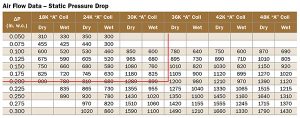
Figure 3 Specific manufacturer data (not for field use)
CFM = 1200 adequate for up to 3 tons of cooling
For electric furnaces use: CFM = volts x amps x 3.414 (Btu/watt) ÷ temperature rise x 1.08
For oil furnaces first calculate heat input rate = nozzle rating x oil heating value. Then do a combustion analysis to determine efficiency. Plug these values into the temperature rise formula.
The temperature rise method requires data collection take place after the system has stabilized without cycling off for at least 10 minutes-this is not going to happen during the summer months. Therefore, a technician will have to utilize other methods to determine airflow.
1. Does the equipment manufacturer supply charts relating airflow to total external static pressure (ESP)? Is the equipment installed in such a way that total ESP can be measured without drilling holes in cabinets and cased coils?
Figure 3 Specific manufacturer data (not for field use)
2. Does the manufacturer supply airflow data based on the pressure drop over a dry evaporator coil thus eliminating the need to run a temperature rise test?
In Figure 3 (note, this cannot be applied to any other evaporator coil), a pressure drop of 0.2 in. w.c., when measured over a three-ton coil, is equal to 1200 cfm.
3. Does the manufacturer provide airflow data related to specific accessories such as a cabinet style air filter?
For example, the filter in Figure 4 has manufacturer supplied pressure drop data that can be manually charted for easy reference. When the filter is clean and the fan is running at rated speed for a three-ton system, the pressure differential over the filter should be 0.15 in. w.c. indicating air is flowing through the filter at a rate of 1200 cfm.
COOLING SYSTEM OPTIONS
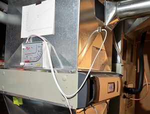
Figure 4 Horizontally mounted cabinet-style air filter
Electronic thermostats have evolved into more than just binary system controllers, especially communicating controls. Assuming a residential HVAC contractor sells a premium cooling system or heat pump featuring two-stage cooling, staged or modulating heating with variable speed fan motor and compressor, all the additional control features ought to be explained to the end user. Optional thermostat control functions selected by the homeowner should then be given to the installer for configuration prior to start-up.
1. A communicating thermostat may be working with a single stage outdoor unit that is connected to a variable speed air handler by way of an interface. In this case, comfort options might be limited to a brief dehumidification cycle such as up to a one minute fan-off delay at the start of a call for cooling. Why not engage this option for increased humidity control?
2. With staged or VRF outdoor equipment, fan delays can get complicated. If offered, should full fan operation in first stage be delayed for three minutes, or perhaps run the fan at 50 per cent speed initially? Another available option might be a 30 second delay using 35 per cent of full fan speed. Humidity conscious homeowners will prefer a drier indoor environment every summer day. No fan delay is typically the default thermostat setting, however, some consumers will experiment by themselves so be prepared to deal with questions from perplexed end users.
3. First stage air flow may be adjustable, if the default setting is 80 per cent, for example, the controller may allow a lower airflow setting to help with humidity control.
4. Accessories such as UV lights, air cleaners, HRVs and humidifiers can also be controlled by some communicating controls. These devices must also be configured to operate with the air handler and under what conditions and at what speed the fan should operate.
5. Many system options require the installation of a matching outdoor thermostat (ODS). Without an outdoor temperature reference, some functions cannot be configured especially those associated with a heat pump.
6. Technicians must understand concepts such as PI control, load values, duty cycles, overshoot clamps, stage thresholds and stage inhibits or other parameters related to any particular product. How does changing the cycle rate (cycles per hour) affect how tightly a control point is respected? If a first stage calls for cooling occurs and the P+I load value for shifting to second stage is 100, then why is the system still in first stage when the load value has increased to 115? Is it because a 10-minute Stage Inhibit is being enforced by the controller? Technicians and installers must familiarize themselves with thermostat control options because the end-user will, sooner or later, start asking comfort related questions. Read the manual and take manufacturer training as needed.
7. TIP: When system comfort options have been selected, initial start-up or seasonal start-up should be initiated in “Test” mode to be sure the compressor and air handler are operating at 100 per cent capacity for checking cooling mode operation and system charge.
SUPERHEAT OR SUBCOOLING
Once an AHRI rated system has been installed, airflow confirmed and comfort options designated, a new cooling system must be leak tested, evacuated and dehydrated in accordance with specific manufacturer instructions and industry standards.
System charge, whether R-22 or R-410a, is measured using the subcooling method for TXV equipped evaporator coils and by the superheat method for metering piston equipped indoor coils.
Because our cooling season is short (but often brutal), spring start-ups can be tricky when the condensing temperature is low and there is no evaporator load in the building. Be sure to follow the appropriate manufacturer’s instructions for minimum test conditions. To paraphrase the old proverb, the proof of our pudding is in the cooling. <>
Ian McTeer is an HVAC consultant with 35 years experience in the industry. He was most recently a field rep for Trane Canada DSO. McTeer is a refrigeration mechanic and Class 1 Gas technician.
Data Collection
• Collect the following data on new split system start-ups:
• Condenser air entering temperature °DB and air leaving temperature °DB
• Evaporator air entering temperature °DB & °WB
• Evaporator leaving air temperature °DB & °WB
• Suction line temperature
• Liquid line temperature
• Suction Pressure
• Head Pressure
• Indoor fan speed settings
• Calculated airflow
• High Voltage at outdoor unit LI/L2
• High Voltage at outdoor unit T1/T2
• Compressor amps 100% speed
• Total amps
This data should be left with the unit and updated as necessary at every maintenance check.
FOR ADDITIONAL AC POINTERS FROM MCTEER SEE HPAC MAGAZINE’s MAY 2019 DIGITAL EDITION.

