Air Quality and Energy Efficiency
April 12, 2022 | By Mike Miller
Combining a dedicated outdoor air system with active chilled beams is a modern hydronics solution for well conditioned spaces in buildings.
With the current pandemic seemingly approaching a turning point, we can begin to reflect on the things we have learned, and arguably, we have learned that we could have done much better in one area, and that is to provide much safer indoor environments for everyone.
All of us spend the vast majority of our time indoors, whether at work, school, or in the comfort of our homes. This is where we, members of the HVAC industry can be a part of the solution.
There are several options we can explore to provide safer indoor spaces, and in this article I want to review the use of hydronic system solutions in retrofit or new installations to improve air quality in buildings while also effectively managing energy consumption.
Quickly looking back, after the Spanish Flu pandemic in 1918-1919 building designs changed—more fresh air was introduced to occupied spaces through open windows and such.
And then, when air conditioning was introduced, buildings became more enclosed and mechanical ventilation and energy management became the focus in the design and operations of buildings.
To lower energy costs, ventilation rates were reduced to recommended levels of 12 to 17 cubic feet of air per minute (cfm) per person, depending on building use.
Then COVID-19 came, and in order to make buildings safer for today and the future new recommendations from health and science/engineering agencies (the CDC, ASHRAE, EPA and the WHO) were presented and the following four key recommendations stood out:
1) Dilute: increase ventilation – discussions have been had around raising outside air requirements from 17 cfm to 34 cfm;
2) Exhaust: remove pathogen-laden air by exhausting from the building with fans;
3) Contain: maintaining a relative humidity level between 40-60% creates an environment where bacteria and viruses are limited in both their survival and ability to spread;
4) Clean: COVID-laden particles sizes are between 0.5 and 1.5 microns. MERV 13 filters remove about 85% of particles in this range and MERV 14 removes >90%.
Other suggestions to help with IAQ involve bi-polar ionization and UV lights. The challenge with these solutions is air velocity, meaning the air can be moving too quickly to effectively kill a virus.
So, when we look at these recommendations, by diluting the air (fresh air ventilation) and exhausting (spent air), combined with temperature and humidity control while minimizing air velocity, we can achieve the greatest results.
This leads us into hydronic solutions, and for the purpose of this example, I want to highlight the use of chilled/heated beams in applications because they marry heating, cooling and ventilation in the same device.
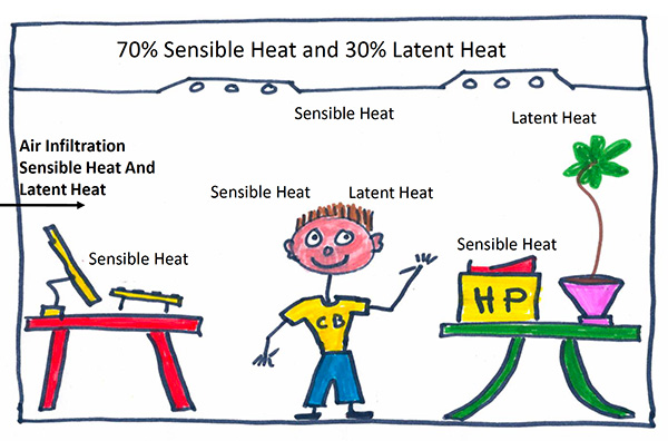
Figure 1: Typical sources of latent and sensible heat in a space.
Typical Cooling Loads
When we look at the cooling load in a space, it is often split with 70% of the load being the sensible heat and 30% being latent heat (see Figure 1, above).
The latent load is basically the humidity in the space that has to be removed. It can come from occupants, air infiltration and it can be introduced with the outdoor ventilation air.
The sensible load is what raises the thermostat and comes from infiltration (like latent), as well as people, computers, and anything in a space that can emit heat.
Most ventilation systems are designed to handle both sensible and latent loads in one piece of equipment: the air handling unit (AHU), fan coil unit (FCU), packaged units, etc.
With chilled beam systems we decouple the latent and the sensible load responsibilities. This is the core design principle that can drive operating savings. The latent load is handled with a dedicated outside air system (DOAS), and the sensible load is handled in the space by the active chilled beams.
As noted, the sensible load is typically 70% of the heat load, and with a chilled beam system there is little to no fan power required to handle the sensible load thus the energy savings.
How Chilled beams work
There are different types of chilled beams; some are simple radiation panels (passive) and others are active chilled beams. Active chilled beams are what we will focus on (see Figure 2).
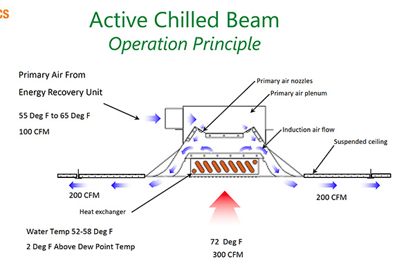
Figure 2. Active chilled beam – operating principle.
These active chilled beams (CB) are induction devices. As the conditioned fresh outdoor air flows from the DOAS through the nozzles in the CB and out through its vents, it induces the air already in the space to flow up through the coil (the heat exchanger) and mix with the incoming conditioned air.
In this example, when in cooling mode, the outdoor air is brought into the CB from the DOAS at a flow rate of 100 cfm (this is the latent cooling and fresh outdoor air required in the space).
Through induction, the warmer space air is induced and flows over the coil and is cooled in the beam. It mixes with the outdoor conditioned air coming from the DOAS and exits the CB.
In this example, the space is using 400 cfm to cool the space, but the only fan horse power (HP) used is associated with 100 of that cfm coming from the DOAS. The remaining 300 cfm is the induced air.
Earlier, it was noted that low air velocity is important in minimizing virus spread. In Figure 3 (below) the image on left is from a test lab space that shows the path of the air coming from a CB. What you are seeing is a Coanda Effect, where because the velocity is low, the air stream hugs the surfaces (ie: ceiling and walls) and then falls through the space.
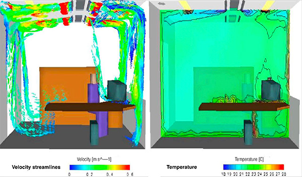
Figure 3: Active chilled beam performance
The graphic on the right also shows the temperature gradient in the space conditioned by CB’s. Again, most of the delta-T in the space is at the vents of the CB. The rest of the space has a very homogenous temperature—comfort without noticeable air movement or noise.
Dedicated Outdoor Air System (DOAS)
As noted, chilled beams are a decoupled system whereby the latent load is handled in the DOAS—the fresh outdoor air is dehumidified as necessary (Figure 4). The sensible load is treated in the space by the chilled beam.
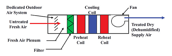
Figure 4: Dehumidification process with the dedicated outdoor air system (DOAS).
In other approaches, like variable air volume (VAV) systems, the latent and sensible loads are handled in the AHU and then distributed through the system.
In a conventional CB design there are two loops, low temperature and high temperature to handle the latent and sensible loads. The schematic in Figure 5 shows a low temp system handling the latent load with operating temps of 42F to 52F.
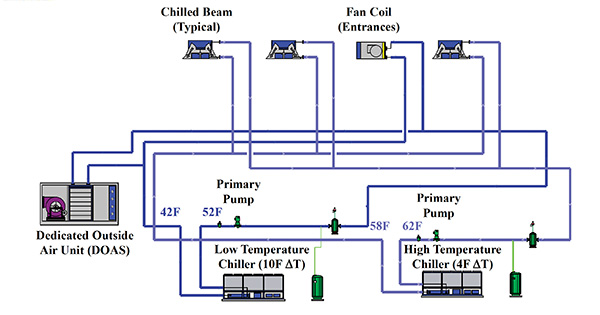
Figure 5: A mechanical example of a four-pipe active chilled beam cooling system.
The DOAS treats most of the latent load, and in this scenario there is also a fan coil at the entrances to handle the instantaneous latent loads.
The high temp system that handles the sensible load typically operates from 58F to 62F. The high temp system operates above the dew point to prevent condensation and typically operates on a four-degree delta T.
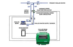
Figure 7: control strategy for one-pipe active chilled beams and DOAS.
This four-pipe system (cooling only, six pipes when you add heating) involves many components and pieces of equipment, notably two chillers with pumps and accessories. It’s worth noting here, there are typically two-way valves at each chilled beam.
Another design option is to combine a single heating/cooling plant and provide local mixing for the two different temperature requirements between the latent loads at entrances and sensible loads at the chilled beams (Figure 6).
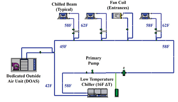
Figure 6: A one-pipe solution with localized mixing at outputs.
This is a primary/secondary hydronics system design. The main loop transports all the Btu’s required to satisfy the entire load of the system when it is operating at 100% design load conditions. We control this loop off of delta T, maximizing the chiller efficiencies.
The secondary loads are piped to the primary loop by closely-spaced tees (or engineered fittings) hydraulically decoupling the secondary loops from the primary. In the first secondary loop a wet rotor circulator, sized to the load of the DOAS, circulates the water. The DOAS is the first load as it will have the biggest load—in this case water enters the system at 42F and leaves at 45F.
The next load is a chilled beam, where we are using some form of mixing device (could be three- or four-way modulating valves, or variable speed injection mixing as shown in this example).
The purpose of mixing the fluid temperature is to circulate water through the chilled beam and maintain the temperature at the beam above the dew point to avoid condensation.
This example shows a LoFlo mixing block, an engineered solution made up of a hydraulic separator and two circulators. The circulator on the chilled beam side circulates the water through the CB at a constant flow.
The circulator on the primary loop side operates at a variable speed to inject enough chilled water to maintain the temperature in the chilled beam above the dew point. As the water circulates through the primary loop the temperature cascades as it passes each secondary load. As long as the system is sized to handle all of the loads, the system will satisfy each load.
Control Strategy
The right control strategy is critical, and each room is controlled by a specific chilled beam controller (Figure 7).
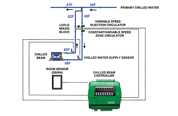
Figure 7: Control strategy for one-pipe active chilled beams and DOAS.
It is required that we monitor several key things:
1) the conditions of the air coming in from the DOAS unit—temperature and humidity;
2) the space conditions, temperature and dew point;
3) then look at the water temperature feeding the CB;
4) assuming conditions are safe to operate, the system ensures just enough chilled water makes it to the beam;
5) continuously monitor all of these conditions adjusting as necessary;
6) if the dewpoint changes, we have the ability to track the supply water temperatures to the beam to ensure condensation doesn’t develop on the CB;
7) if conditions are not conducive to operation, the system will shut down to prevent condensation
Summary
In brief, here’s a summary of the design considerations for a one-pipe active chilled beam solution:
- size the DOAS for largest of loads (it handles the latent load);
- consider fan coil units around entrances;
- control entering chilled water to beams at 5F above dew point;
- design for 4 to 5-degree delta T for chilled beam but keep the primary loop at 14 to 16-degree delta T;
- and consider single pipe injection pumping to maximize energy savings.
In a follow-up to this article we’ll analyze the potential efficiencies of an active chilled beam system as described here in a commercial building application. <>