
Appropriate Emitters
November 2, 2021 | By John Siegenthaler
How to combine multiple heat emitters to suit building and client requirements in an efficient and effective way.

(illustration: Visual Generation/iStock / Getty Images Plus)
One of the benefits of modern hydronic heating is being able to use multiple types of heat emitters in the same system. A common example is a heated floor slab in a basement and fin-tube baseboard on the main living level(s) above. When the fin-tube baseboard is sized around “traditional” design water temperatures (170-200F/77-93C), the system is going to need a mixing assembly to lower the water temperature supplied to the floor heating circuits.
I’ve had the opportunity to design many systems using multiple mixing assemblies to create multiple supply water temperatures for different parts of the distribution system. Although this can work, all the hardware required definitely adds to the system’s cost and complexity. This should lead designers to consider if, in some applications, multiple types of heat emitters could be operated from a single supply water temperature.
Recent Project
We recently designed such a project for rather discerning clients. They had definite ideas on how heat would be delivered to each area of their new home. On the main living level they wanted floor heating for the kitchen, dining room and two bathrooms. They also wanted floor heating in the slab of a breezeway that connected the house to the garage.
The bedrooms and living room floors would be finished with padded carpet, which from a practical perspective ruled out floor heating for those areas. After discussing alternative heat emitter options with them, they decided to use individually-controlled panel radiators in these areas.
This combination of heat emitters would be supplied from a geothermal water-to-water heat pump, the performance of which is strongly influenced by the water temperature leaving the condenser. The lower the load water temperature can be, while still maintaining comfort in the house, the higher the heat pump’s coefficient of performance (COP), and the higher its heating capacity.
The heat pump used in the system was capable of producing water temperatures up to about 125F/52C, but lower is always better when it comes to COP. [reminder: COP is the ratio of useful heating (or cooling) provided by a heat pump relative to the energy required—a higher COP equates to higher efficiency.]
Piping Design
We decided to use a tube and plate radiant panel construction under the subfloors of the kitchen, dining room and bathrooms. The ½-in. PEX-AL-PEX tubing was spaced 8 in. apart. Aluminum plates (5 x 24 in.) were fit over the tubing and tightly stapled to the underside of the subfloor. Fiberglass batts (6-in. thick) were installed directly under the tubing and plates. The basement space beneath these areas was fully heated.
The floors in the kitchen and dining areas would be finished with ½-in.-thick engineered hardwood. The floors in the bathrooms would be covered with ceramic tile over 5⁄16-in.-thick Ditra XL anti-fracture membrane. The floor areas in the bathrooms were small enough that a single tubing circuit could easily accommodate the entire heated floor area. The finishing touch was a towel warmer in the master bath.
Dry Floor
The breezeway is an area where snow and rain will be tracked in from outside, and thus a floor that can rapidly dry is desirable. This area also has a relatively high ratio of exposed thermal envelope area per square foot of heated floor area. There would also be some “cubbies” on the floor to store outside clothing, which would partially inhibit upward heat transfer from the floor.
The upward heat flux at design load was about 45 Btu/h/sq.ft. To handle this we spaced the tubing at 6-in. centres, and decided we could operate this circuit in parallel with (and thus at the same supply water temperature) as the underfloor tube and plate circuits in the kitchen and dining room areas.
All the heat emitters described above are served by a homerun distribution system using ½-in. PEX-AL-PEX tubing. At design load conditions (-10F/-23C outside) all emitters will operate with a calculated supply water temperature of 115F/46C.
Do this, do that
Next came the control requirements. The clients wanted a simple “mode” switch with heat/off/cool settings. When that switch is set for heating, the geothermal heat pump maintains warm water in the buffer tank, ready to flow to any active heat emitter.
The kitchen, dining room and living room are one large open space. As such it made no sense to try to independently control temperature at each heat emitter. The floor heating in the kitchen and dining room areas would operate at the same time as the two panel radiators in the living room. The breezeway circuit would also be operating in parallel with these emitters.
We combined the three floor heating circuits with the two homerun circuits for the panel radiators. All these circuits begin and end at a single manifold station. That manifold station is supplied through a ¾-in. zone valve tied to the living room thermostat.
The panel radiators in the bedrooms each respond to integrated non-electric thermostatic radiator valves.

Figure 1. Wall mounted knob that acts like a non-electric thermostatic valve on a radiator.
The floor heating in one bathroom is also regulated by a thermostatic valve that’s cut into the supply side of the single floor heating circuit and located under the floor. It can be accessed through a small panel in the basement ceiling. A stainless steel capillary tube runs from this valve to a wall mounted knob (see Figure 1), which is used to sense and regulate room temperature, just like a non-electric thermostatic valve on a radiator.
The master bathroom floor is also heated by a single circuit that first connects through the towel warmer and then continues on under the floor. Flow in this circuit is regulated by another non-electric thermostatically controlled underfloor valve connected to a wall mounted knob by a capillary tube.
The overall topology of the heating distribution system is shown in Figure 2 (below).
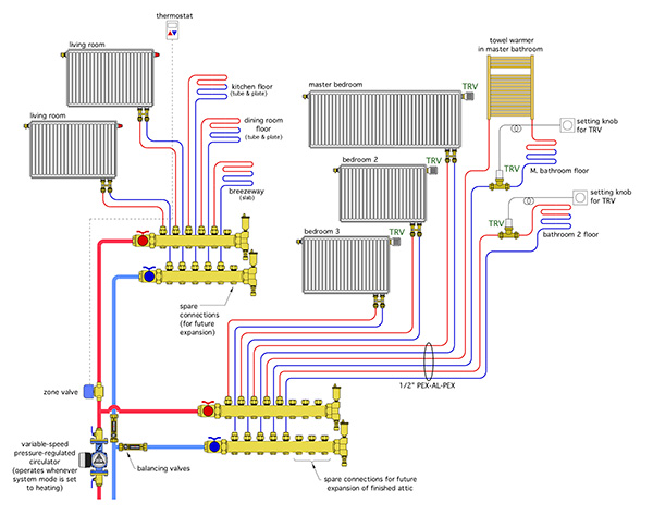
Figure 2. Topology of the heating distribution system.
Flow Control
Balancing valves with integral flow meters are installed in both main branches of the distribution system. Flow is provided by a single Taco 0018e variable speed pressure regulated circulator that’s “active” whenever the mode selection switch for the system is set to heating. The input power to this circulator varies from 4 to 44 watts depending on speed. This circulator automatically adjusts its speed in response to the opening and closing of the zone valve on one manifold station, or any of the non-electric thermostatic valves supplied through the other manifold station.
This system is currently maintaining comfortable conditions in all areas using an average supply water temperature of only 105F/40C. The heat pump turns on when the buffer tank temperature drops to 100F/38C and off when that temperature reaches 110F/43C.
Based on manufacturer’s ratings, the heat pump operating under these load side conditions and with fluid returning from the horizontal geothermal loop at 50F/10C, will have an average COP of 3.1 (excluding the power draw of the two high efficiency circulators used on the heat pump, which total to about 250 watts). If the circulator wattage is included the “net” COP is about 2.97.
Fixed temperature range vs. outdoor reset
You may be wondering why we didn’t use outdoor reset control for the tank temperature, which would allow for lower water temperatures, and higher COPs under partial load conditions.
The reason we stayed with the 100-110F (38-43C) temperature range was to allow domestic hot water preheating using the thermal mass of the 119-gallon buffer tank.
Whenever there’s a draw for hot water of 0.7 gpm or higher, a flow switch activates a small circulator that routes heated water from the top of the buffer tank through a 5 x 12 x 40-in. plate stainless steel heat exchanger. Cold domestic water makes a single counterflow pass through the other side of this heat exchanger. The preheated domestic water flows to the cold water inlet on a 40-gallon electric water heater for a “top off” in temperature. The preheating piping components are shown in Figure 3 (below).
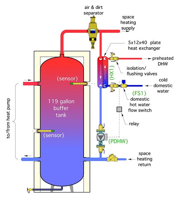
Figure 3. DHW preheating piping design.
Simple yet elegant
This distribution system, though unique to meet specific owner requirements and building details, was assembled from off-the-shelf hardware.
The tube and plate floor heating, the heated slab in the breezeway, the panel radiators and the towel warmer, in combination with the design heating loads in the spaces these emitters serve, allowed for a single supply water temperature eliminating the need for mixing. That temperature also ensured that the geothermal heat pump would operate at relatively favourable conditions.
The system can respond to internal heat gains or comfort preferences, such as lowering bedroom temperature at night, while at the same time maintaining warm bathroom floors and luxurious dry towels.
The comfort offered by the individual “niceties” in this system could never be matched by ductless heat pumps or other types of forced air systems, and the owners are looking forward to many years of superior comfort. <>

John Siegenthaler

