
Back in the Day
January 20, 2021 | By Dave Demma
Retelling of an early service call to solve a grocery store’s meat freezing issue that required deductive reasoning, a look at the manuals and a sense of touch.

(photo: Getty Images)
Back in the day…way back in the day…after graduating from college, I started my career in this industry as a technician.
In spite of my newly-earned engineering degree, I just didn’t fancy myself sitting behind a desk. I like working with my hands, and I was very intrigued to gain a real-world experience to complement my book-learning experience.
In my early technician career I was employed by a large contractor whose main focus of business was supermarkets.
One particular day I was sent to the QFI supermarket in San Mateo, California. The complaint: the fresh meat was freezing.
Now, this was an older store that was probably built in the 1960s. Their equipment was not “state of the art”. Each system had its own separate condensing unit, and the controls were simplistic. This particular system was utilizing R-12, and the method of temperature control was simply a low-pressure control.
Because there is a defined relationship between refrigerant pressure and refrigerant saturation temperature, a pressure control (set correctly) can provide moderately acceptable temperature control.
However, the best control will always be maintained when sensing the particular parameter which is to be maintained (as opposed to sensing a parameter that has a correlation to the parameter being maintained).
The low-pressure control’s approximate settings would have been as follows: cut-in setting of 27 psi (28.4F saturation temperature), and cut-out setting of 14.5 psi (10F saturation temperature).
After connecting my gauges, I found that the compressor was chugging along at a suction pressure of 21psi (20F). This was nowhere near the 14 psi cut-out, yet the discharge air in the display case was low enough to freeze the meat.
After watching the system operate for a little while, it was noticeable that the suction pressure was not falling below the 22 psi range. In other words, this compressor was doing all it could, maintaining a constant 22 psi suction pressure…but lacking sufficient capacity to bring the suction pressure anywhere near the control’s cut-out setpoint.
This is where some detailed analysis can assist with a diagnosis, but it involves looking at the performance data for the compressor (which is typically available online for the compressor manufacturer).
There are several things which will determine the compressor motor amperage; voltage supply, voltage drop (due to excessive resistance in the wire connections or starter contacts), and anything that increases the load on the motor—internal compressor resistance (bearings and/or rings), and changes in suction and/or discharge pressure (which influences the compression load on the pistons).
Referring to the specification chart for the 9RS3-076A-TFC (Figure 1, below), for varying SST and SCT conditions, it lists the following compressor performance specifications:
- C Capacity in Btu/h
- P Power in Watts
- A Current Amps
- M Mass Flow in Lbs/Hr
- E EER in Btu/Watt-Hr
- % Isentropic Efficiency
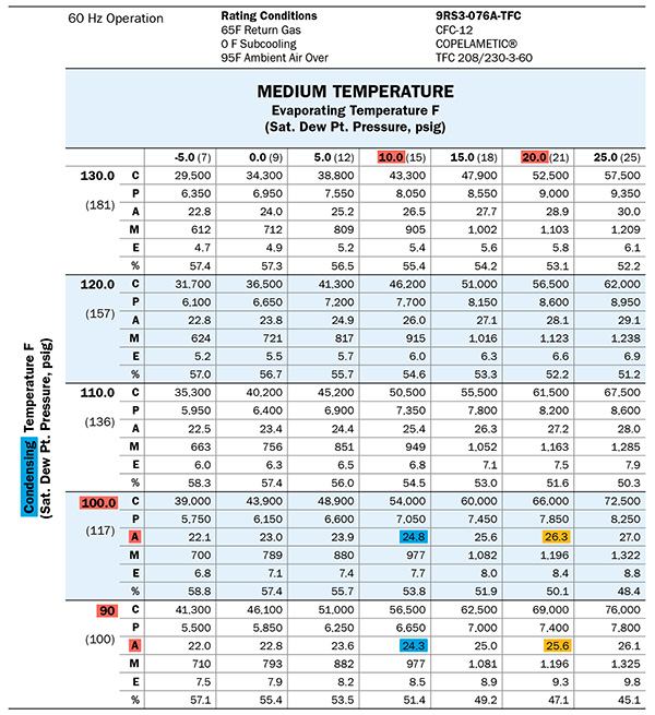
Figure 1.
We are focusing on compressor motor amperage, specifically in tandem with SST and SCT.
All other system parameters remaining equal:
- As the suction pressure increases, the compressor motor amperage will increase. This is due to the fact that density (lb/ft³) increases as the suction pressure increases. With a given cylinder displacement, the greater the vapour density, the greater the refrigerant mass flow. It would make sense that it would require more energy (amperage) to deliver a higher mass flow.
As noted in the chart above, at a 10F SST and 90F SCT, the compressor motor amperage is 24.3 amps (highlighted in blue). Increasing the SST to 20F SST, the compressor motor amperage increases to 25.6 amps (highlighted in yellow).
- As the discharge pressure increases, the compressor motor amperage will increase. This is the result of the pistons being required to compress to a higher pressure, which requires more work, and that comes in the form of electrical energy (amperage).
Again, according to the chart above, at a 10F SST and 90F SCT, the compressor motor amperage is 24.3 amps. Increasing the SCT to 100F, the compressor motor amperage is 24.8 amps (highlighted in blue).
Now, the compressor in this particular service call was operating at a 20F SST and 100F SCT. The compressor motor amperage should have been 26.3 (highlighted in yellow). But it was somewhere in the range of 18.
Something did not add up, as the amperage was much lower than the manufacturer’s data states it should have been. A series of logical deductions, based on the data, will suggest the cause:
- Compressor amperage is the result of compressor loading.
- The compressor is operating at a 20F SST, which is well above the low-pressure control cut-out set-point. This would suggest that the compressor is under a high load.
- The compressor motor amperage is well below what it should be for the condition, which suggests that the compressor is operating at a low load condition.
And now, let’s add a little additional information.
- The 9RS3 is a three-cylinder compressor. Typically, the head above each cylinder is too hot to touch. But, the head above the front cylinder was lukewarm to the touch.
- The compressor was also operating with a noticeable vibration. This is not ordinary.
My deduction was that one of the three cylinders was not doing any work. That would explain the lukewarm head, the reduced amperage, and depending on the cause of the ineffective cylinder, could also explain the vibration.
Removing the compressor head revealed that the front cylinder was half full of oil. On these smaller semi-hermetic compressors you can alternately push down on one cylinder, then another, and it will turn the crankshaft. Doing this revealed that pistons #2 and #3 were connected to the crankshaft, and moving up/down along with the crankshaft rotation. But piston #1 never moved.
Boom….broken connecting rod! (see Figure 2)
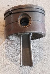
Figure 2. Piston with broken connecting rod.
The interesting thing about this broken connecting rod is that it happened in such a manner that the compressor was able to continue to rotate without any obstruction from the broken parts. The remaining attached portion of the rod on the crankshaft caused an imbalance which resulted in the compressor vibration.
Now, let’s think about this for a moment. A three-cylinder compressor, with one cylinder inoperative, has become a permanently unloaded two-cylinder compressor.
Rather than 100% compressor capacity, it is now 66.67% compressor capacity.
But, this caused the normally 34F meat in the display case to freeze. How could this happen?
The compressor was a little oversized for the application, so the loss of 1/3 of the compressor capacity didn’t result in the product never reaching its desired temperature. The real cause of the freezing was the fact that a low-pressure control was used as the means for maintaining temperature.
With the broken connecting rod, the compressor did not have enough capacity to bring the system down to the cut-out point. So, it operated non-stop, with 28F air blowing on the fresh meat all day long (except during the periodic defrost cycles). Of course, the meat froze.
To take this a step further, had the means of temperature control been a thermostat, this likely would not have resulted in a service call.
But, it did result in a service call. And, it provided a good opportunity for a young technician to learn a little more about troubleshooting, analytical thinking, and not giving up until a cause was found.
And the experience also illustrated the benefit in using the manufacturer’s performance data as a comparative means to determine how your equipment is performing. <>
 Dave Demma holds a degree in refrigeration engineering and worked as a journeyman refrigeration technician before moving into the manufacturing sector where he regularly trains contractor and engineering groups. He can be reached at ddemma@uri.com.
