
Make the right choice: An overview of new plumbing and hydronic valves
October 26, 2018 | By Kevin Freidt and Mark Olson
Several manufacturers have introduced new balancing valve technologies into the market. Familiarity with these new valves, as well as traditional balancing valves, will assist you in selecting the correct one for specific hydronic and plumbing system applications.
MANUAL BALANCING VALVES
Manual (a.k.a. pressure-dependent) balancing valves with two ports for measuring differential pressure across an internal orifice have been industry workhorses for decades. They are sometimes called “static” balancing valves because once adjusted there is no movement of parts inside the valve.
There are two types of manual balancing valves: the fixed orifice (FO) type and the variable orifice (VO) type. Orifice refers to the portion of the valve located between the two ports used to measure differential pressure.
Fixed orifice balancing valves
In a FO valve there is no change in internal geometry between the differential pressure ports–the orifice remains fixed while the valve is being adjusted.
A direct relationship exists between pressure drop across the ports and flow rate. That relationship is governed by the following formula: Where: Q is flow rate (in gpm), Cv is the flow coefficient of the orifice between the ports, ΔP is the pressure drop across the ports in psi.
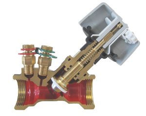
Figure 1 Fixed orifice , 3/4 in.
For example the manufacturer’s published Cv value for the valve in Figure 1 is 6.4. If the ΔP across the ports is measured as 0.3 psi, then the calculated flow rate is shown on the right. To eliminate the need of installers doing this calculation, manufacturers plot the relationship on wheels or charts to allow fast determination of flow rate. Figure 2 shows a chart for the valve shown in Figure 1. The red lines show how the previously calculated flow is determined.
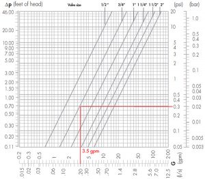
Figure 2 Flow versus pressure drop chart
Special instruments are used to measure differential pressure across FO and VO balancing valves. Figure 3 shows a FO balancing valve connected to a digital manometer using small hoses. Some manometers can be programmed to directly convert the differential pressure measured across a valve to a flow rate reading.
Variable orifice balancing valves
The second type of manual balancing valve is called a variable orifice (VO) valve.
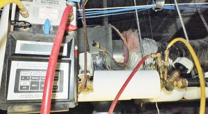
Figure 3 Fixed orifice with manometer hook up
Figure 4 shows an example. As the contractor turns the knob to adjust flow the geometry of the orifice between the pressure ports varies.
Notice that the internal adjustment member of the valve is positioned between the pressure ports. Thus the Cv value of the orifice changes as the valve is adjusted. This makes the procedure for determining flow rate more involved than with a FO valve.
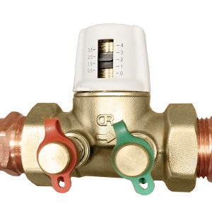
Figure 4 Variable orifice with knob set at 2
Manufacturers publish a family of curves for each size valve. Each curve relates to a specific knob position. Figure 5 shows the family of curves published for the valve shown in Figure 4. The red lines illustrate how a knob setting of 2 combined with a measured differential pressure of 3 psi, indicates a flow rate of 3 gpm.
If this flow measurement of 3 gpm was the first one conducted, and 5 gpm is the desired flow rate for the circuit, the contractor might choose to open the valve to position 3 or 4, determine the new flow rate, and through simple interpolation determine the knob setting that should result in a flow rate close to the target value of 5 gpm. This process would be repeated, as necessary, until the target is attained.
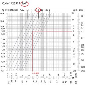
Figure 5 Flow versus pressure drop chart, variable orifice
Balancing a circuit with traditional manual balancing valves is an iterative “trial & error” process. Furthermore because circuits are hydraulically coupled, adjusting flow in one circuit affects flow in the other circuits. A system with 10 circuits can require 60 or more readings and adjustments to achieve the desired flow rates.
Accurate balancing requires skill and experience. Various test, adjusting and balancing organizations exist in North America to train and certify balancing professionals.
Direct reading balancing valves
A variation of the FO valve that was introduced in North American a few years ago does not require ΔP readings, and instead uses a built-in flow meter. The flow rate is directly read by the balancing technician. This type of valve is generally more expensive than traditional manual balancing valves, but can simplify balancing, reduce balancing labour time significantly, and eliminate errors. Figure 6 shows an example.
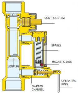
Figure 6 Direct reading manual balancing valve
Within this type of valve a bypass channel connects to both sides of a venturi. To set the flow rate the balancing technician pulls the ring on the bypass valve which allows flow through the bypass channel. A spring/disc mechanism travels within this bypass channel, its position relative to flow rate. The disc is magnetic and attracts a small steel bead located within an external sealed glass cylinder. The cylinder graduations are calibrated so that the bead location indicates the valve’s flow rate.
To set flow rate, the balancing technician simply rotates the control stem with a wrench while viewing the meter until reaching the target value, then releases the ring. Circuit flow can be set in a fraction of the time required for traditional manual balancing valves. Furthermore, common sources of error such as incorrectly calibrated instruments, misinterpreting pressure readings, incorrectly interpolating logarithmic charts, and incorrectly interpolating adjustment knob positions can be eliminated.
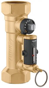
Figure 6
In DHW recirculation systems, the calculated branch flow rates required to maintain a minimum temperature at the farthest fixture are frequently so low that they are difficult or impossible to read using traditional manual balancing valves that rely on differential pressure. For a given flow rate the differential pressure across a VO valve is greater than that of a FO valve–seemingly giving the advantage. But an offsetting factor is having to interpolate based on adjustment knob position.
Because of these advantages, direct reading manual balancing valves are becoming more common in DHW recirculation applications. Figure 7 shows an example of one on a DHW return riser. Notice the minimum graduation of ½ gpm. This is a commonly specified circuit flow rate, and low enough that it is often difficult to accurately set using a traditional differential pressure type balancing valve.
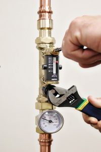
Figure 7 Direct reading manual balancing valves on a DHW return riser
AUTOMATIC BALANCING VALVES
Figure 8 shows a type of balancing valve type often referred to as an automatic (that is pressure independent) balancing valve. Unlike a manual balancing valve, an automatic balancing valve has internal parts that move as differential pressure across the valve changes. Because of this these valves are sometimes referred to as dynamic balancing valves.
PRESSURE-INDEPENDENT BALANCING VALVES
Other balancing valves technologies now exist that also have moving parts. They include thermal balancing valves and pressure independent control valves. These valves are also automatic. So the simple descriptor of “automatic” is no longer sufficient. We like to refer to the valve type shown in Figure 8 as a pressure independent (PI) balancing valve (to differentiate it from a thermal balancing valve).
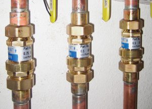
Figure 8 PI balancing valve
Unlike a static balancing valve, a PI balancing valve controls flow rate within a circuit to a fixed value as long as the pressure drop across the valve is within a specified working range. It does so using a cylinder-piston-spring cartridge assembly within the valve. As differential pressure across the valve increases from 0 to the minimum value of the working range, flow increases proportionally.
Up to this condition the piston within the valve has not yet moved. However, as differential pressure continues increasing, the piston begins compressing against the spring (Figure 9), reducing the “characterized” flow aperture area and keeping flow at rated value. This regulation process continues as pressure increases to the maximum differential pressure value of the working range. As long as differential pressure falls between the min and max values (that is the “working range”), the flow rate through the circuit stays at rated value. In a multi-branch system, pressure independent valves maintain a stable flow rate within each branch as flow in other branches cycle on and off or modulates.

Figure 9 Cylinder-piston-spring flow cartridge assembly
Because PI valves are supplied with a calibrated flow rate setting, configured at the factory, they are essentially pre-balanced. The circulator simply needs to be sized so that the pressure drop across the valves is within the working range.
Several designers prefer PI valves over manual valves to simplify commissioning. This holds for plumbing applications as well, and thus low-lead rated PI balancing valves are available.
THERMAL BALANCING VALVES
An intriguing type of balancing valve is known as a thermal balancing valve (TBV), which is offered by two or three manufacturers in North America. We expect more manufacturers to begin production of these valves in the near future.
A TBV modulates flow rate within a circuit in order to maintain a fixed temperature at the valve. In recirculating domestic hot water (DHW) plumbing systems this is significant because unlike hydronic applications where balancing is intended to control heat transfer, in recirculating DHW systems balancing is done to ensure adequate water temperature at the fixtures. TBVs are a temperature solution for a temperature problem.
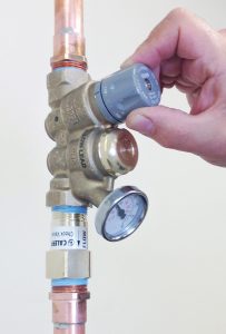
Figure 10 Field adjustable thermal balancing valve
Both fixed temperature and field adjustable temperature types are available. Figure 10 shows a contractor adjusting a field adjustable type within a circuit return riser.
In a thermal balancing valve an internal thermostatic cartridge expands and contracts in response to the water temperature passing through the valve. When cool water is passing through, the valve is fully open. As water temperature rises, the valve begins to close down until the temperature reaches the user-set value. At this position the valve allows minimal flow, just enough for ongoing temperature sensing.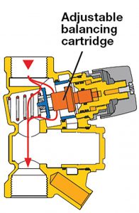
If the entering water temperature begins to decrease, which occurs when there is minimal DHW demand, or from water heater draw down, the valve begins to open allowing higher flow through the branch.
This continual expansion/contraction action of the TBV ensures water temperature control within each recirculating branch over a wide range of DHW demand. When combined with a variable speed circulator operating in constant pressure mode, TBV valves can result in sizable pumping energy savings too.
Whether embarking on a new hydronic or plumbing system project, accurate flow balancing is paramount to achieving design objectives. The balancing technologies mentioned here offer solutions for specific balancing requirement(s). The key is in selecting the right one for the job. <>
Kevin Freidt is director of product management and technical support with Caleffi North America. He has a BS Mechanical Engineering Technology and is LEED accredited v2.0. Mark Olson is general manager of Caleffi North America, Inc. Olson has a master of science in engineering, applied mechanics and a bachelor of science in engineering, industrial and operations engineering. To see other articles by this author visit www.hpacmag.com.

