
A basic pellet boiler retrofit
March 6, 2018 | By John Siegenthaler
 Over the last four years I have been reviewing submittals for proposed heating systems using pellet boilers. They come from heating professionals ranging from contractors to professional engineers. These submittals are required to participate in an incentive program that offers significant rebates to encourage growth of the biomass heating market.
My task is to review the proposed systems for technical details and flag possible issues for clarification or redesign, before thousands of dollars of hardware gets installed incorrectly.
A common scenario is that many designers view pellet boilers as simply a box that burns pellets and makes hot water. They want to set that box next to an existing oil-fired or propane-fired boiler and just cut it into the existing distribution system. They seldom look at that existing distribution system as fertile ground for not only improving the performance of that new pellet-burning box, but also improving the comfort provided by the system.
What follows describes the “makeover” of an existing oil-fired hydronic heating system, which was chosen to receive a modern pellet boiler. This makeover shows one way to integrate the new boiler so that its unique operating characteristics are respected. It also shows how the “comfort challenged” heat delivery system was improved at the same time.
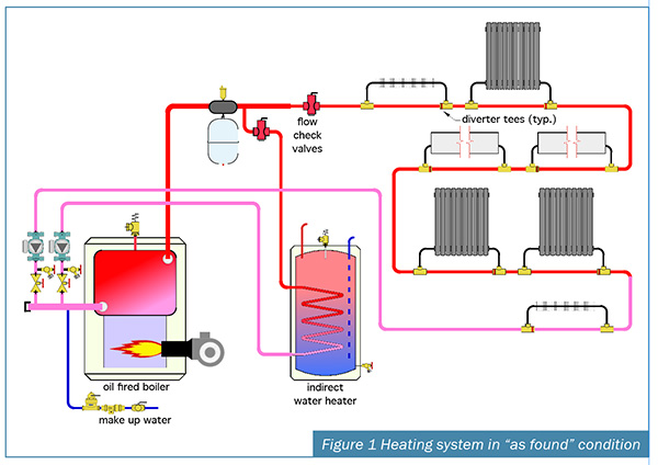
This makeover is based on a real installation. It took place in an 1800s vintage farmhouse in a cold upstate NY location. Figure 1 shows a piping schematic of the original system.
The oil-fired boiler supplies a single distribution circuit that serves a combination of fin-tube baseboard, standing cast-iron radiators and some cast-iron baseboard. Yes, someone really put all those different heat emitters together on a single circuit. The heat emitters are connected to the piping circuit using diverter tees.
When interviewed prior to the makeover, the homeowner stated there were several “cold spots” in the house. In fact, those spots were cold enough to freeze a glass of water left on the kitchen floor over a winter night. Ouch.
GOING UNDER THE KNIFE
 The primary goal of the makeover was to reduce heating cost by adding a modern pellet boiler to this system and treating it as the primary heat source. The oil-fired boiler would remain in the system as the auxiliary heat source. The intent was to configure the oil-fired boiler to automatically operate if the new pellet boiler was unable to supply the load, or was out of service.
At the time of the makeover, heat supplied from the new pellet boiler would be about half the cost of heat supplied by burning fuel oil. However, those cheaper Btus were not going to allow the marginal hydronic distribution system to improve the homes’s comfort. This is where the scope of the makeover changed from simply reducing operating cost to also providing significantly improved comfort.
The rational behind this makes sense: Since the system would be undergoing significant hydronic “surgery” to add the new boiler, why not use that opportunity to upgrade the home’s comfort by adding some more heat emitters while the system is on the “operating table?”
An easy way to do this was to install a manifold station in the basement and use it along with ½ in. PEX-AL-PEX tubing to supply panel radiators placed in the areas where comfort was marginal. The panel rads could be different sizes to match the supplemental heating needs and available wall spaces of the cold areas. The manifold station would even include two additional connections, which were to be closed off initially, but easily accessible if the system was ever expanded further.
Beyond improved comfort, the added heat emitters would lower the water temperature at which the distribution system could supply design heating load. A suggested guideline is to add enough heat emitters to reduce the supply water temperature at design load conditions by at least 30F (that is, from 180F on an existing system to 150F on the modified system). This allows the thermal storage tank that is an integral part of the pellet boiler retrofit to operate over a wider temperature cycling range. The result is reduced on/off cycling, which yields higher thermal efficiency and lower emissions.
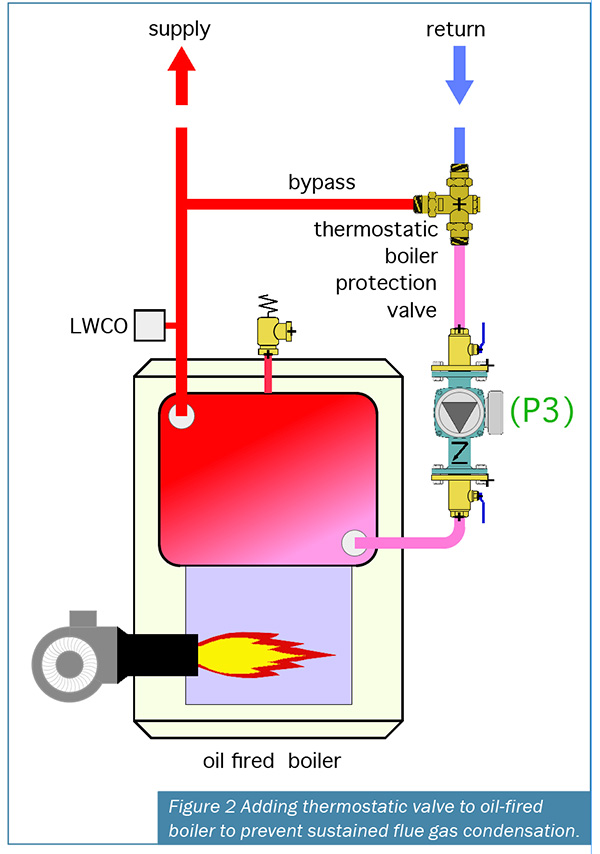
Another suggested guideline is to limit the added heat emitters so that the return water temperature to the oil-fired boiler stays above 120F most of the time. This should be sufficient to prevent sustained flue gas condensation within the oil-fired boiler.
If the return water temperature will be consistently below 120F, as it might if a large area of radiant panel heating were added to the system, it is prudent to add a thermostatic boiler protection valve as shown in Figure 2. When necessary, this valve limits flow through the oil-fired boiler to keep it from operating with sustained flue gas condensation. With this valve in place, along with another anti-condensation valve for the pellet boiler, the return water temperature from the distribution system can be as low as you want.
THE MAKEOVER
 Figure 3 shows the modified system, which now includes the pellet boiler and thermal storage tank along with some other piping modifications.
This reconfiguration allows either the thermal storage tank, or the existing oil-fired boiler to deliver heated water to the closely spaced tees that hydraulically separate circulators (P2 and P3) from the zone circulators. It also allows the oil-fired boiler to be isolated from heated water when it is not being used, which should be most of the time now that the pellet boiler is installed. This is important because allowing heated water to flow through an unfired boiler just dissipates heat through that boiler’s jacket and up its flue.
The pellet boiler operates completely independent of any call for heat from the building’s thermostats. This is very different from the common demand fired boilers most hydronic heating pros are used to, where the boiler only operates if there is a demand for heat from a building thermostat.
The pellet boiler is operated by its internal controller, which monitors the temperature of two temperature sensors (S1 and S2) within the thermal storage tank. When the temperature at the upper sensor (S1) drops to a setpoint, such as 140F, the pellet boiler fires and circulator (P1) turns on. The pellet boiler and its circulator remain on until the temperature at the lower tank sensor (S2) has climbed to some high temperature limit such as 170F. This stacks the tank full of hot water before the boiler is turned off.
The objective is to create long on-cycles followed by long off-cycles, which increase the burn cycle efficiency of the pellet boiler and reduces its emissions. The pellet boiler operates as described above whenever its main power switch is turned on, which is typically at the beginning of the heating season. The switch is turned off at the end of the heating season.
The controller within the pellet boiler also operates a three-way motorized mixing valve installed between the boiler and thermal storage tank. This valve’s purpose is to keep the boiler’s inlet water temperature above the dewpoint of the combustion gases (about 130F) whenever possible and thus prevent sustained flue gas condensation.
BASIC BRAINS
The control system that manages overall system operation is straightforward. Whenever there is a demand for space heating or domestic water heating, power is applied to a temperature setpoint controller that measures the water temperature in the upper portion of the thermal storage tank at sensor (S3). If that temperature is at or above some minimum value, such as 140F, circulator (P2) is turned on and heat is supplied from the tank to the load.
If the water temperature in the upper portion of the tank is below this setpoint, circulator (P2) is off and the oil-fired boiler is turned on along with circulator (P3). If the temperature at the top of the thermal storage tank later rises to the minimum setpoint plus a differential of 10F (in this case 140F+10F=150F), the setpoint controller brings the tank back online as the sole heat source. Note that circulators (P2) and (P3), as well as all the zone circulators, have internal check valves.
The new circulator that supplies the manifold station is wired in parallel with the original zone circulator supplying the space heating distribution system. This ensures adequate flow and head to handle the new panel radiators.
BABY STEPS
This is a relatively simple makeover scheme. There are more elegant ways to determine if the thermal storage tank, the oil-fired boiler, or even both, should supply heat to the system. These involve control concepts such as outdoor reset, variable speed injection mixing and differential temperature measurement. They improve thermal performance, and they also add cost and complexity to the system.
Incorporate these more advanced control methods will be the subject of future columns.
 John Siegenthaler, P.E., is a mechanical engineering graduate of Rensselaer Polytechnic Institute and a licensed professional engineer. He has over 34 years experience in designing modern hydronic heating systems. Siegenthaler’s latest book is Heating with Renewable Energy (see www.hydronicpros.com for more information).

