
Chiller Control Options
June 19, 2020 | By Dave Demma
In addition to comfort cooling, there are many commercial and industrial uses for chillers ... the list is almost endless.
It probably goes without saying that anyone involved in the HVAC/R industry likely knows exactly what a chiller is. But for those outside of our industry, if there was ever a word that was completely inadequate in providing an accurate description of a process, it is “chiller.”
How do you even define ‘chill’. Perhaps someone has given you a stare that chilled you. Or have you ever been chilled to the bone? Chill doesn’t even come close to accurately describing a temperature range. But perhaps that’s ok, since there is no average range temperature application for a chiller.
OK, let’s chill out over the word thing, and talk about chillers.
So, what is a chiller? To understand chiller operations it all starts with your basic refrigeration cycle, consisting of:
Compressor
Function: Receive low pressure vapour from the evaporator and convert it to a high pressure vapour. As the compressor also adds heat to the vapour during the compression process, the end result is a superheated high pressure vapour.
Condenser
Function: Transfer heat from the superheated high pressure vapour. First the vapour is desuperheated. Once the vapour reaches a saturated state, further heat transfer allows it to undergo a change of state into a liquid, and then become a slightly subcooled liquid.
Expansion Device
Function: Allow the subcooled high pressure liquid to undergo a pressure drop. The resulting lower pressure will have a corresponding saturation temperature that makes it useful for transferring heat from the refrigerated/conditioned space (or load).
Evaporator
Function: Transfer heat from the refrigerated/conditioned space (or load) to the low pressure, low temperature saturated liquid refrigerant, flowing through the evaporator.
The load on a typical evaporator in a refrigeration/air conditioning system is the heat content in the air from the refrigerated/conditioned space.
The typical evaporator is a finned tube fan coil design. Heat from the air flowing through the finned tube evaporator is transferred to the refrigerant flowing through the evaporator tubes, resulting in a lower air temperature in the refrigerated/conditioned space.
What I’ve described is a typical single stage of heat transfer: heat from the refrigerated/conditioned space to the primary heat transfer fluid (refrigerant).
A chiller is quite different, in that it involves two stages of heat transfer. The heat load on the chiller’s evaporator is a secondary heat transfer fluid, such as water, or a mixture of water and propylene glycol.
This secondary fluid is brought down to the design temperature for the particular application, and is then pumped to secondary heat exchangers in the refrigerated/conditioned space.
The heat load from the actual refrigeration/conditioned space load is transferred to the pumped secondary heat transfer fluid. This heat is then transferred to the refrigerant flowing through the chiller’s evaporator.
There are two main types of heat exchangers (evaporators) used in chillers:
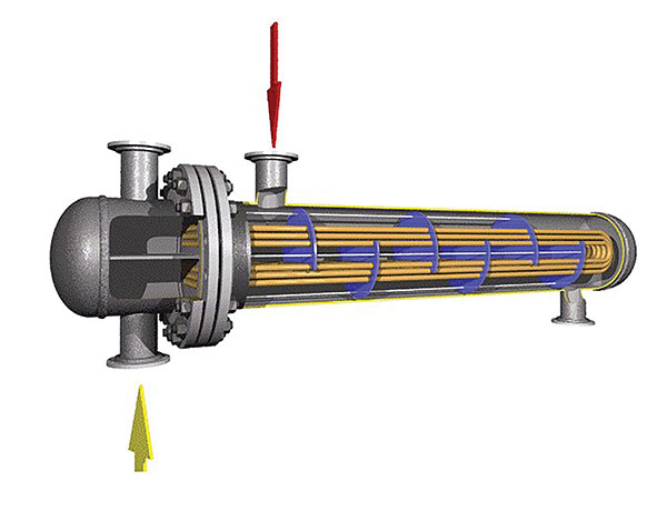
Shell and Tube Heat Exchanger
In a shell and tube heat exchanger (pictured above), the lower temperature saturated liquid refrigerant flows through the inside of the tubes in the barrel, and the secondary fluid is also pumped through the barrel. As the secondary fluid makes contact with the tubes, heat is transferred from it to the refrigerant flowing inside the tubes.
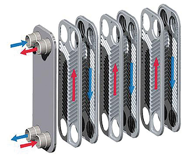
Brazed Plate Heat Exchanger
In a brazed plate heat exchanger (above), a series of corrugated plates are fastened together in a frame. The channel formed by two adjacent plates facilitates the heat exchanger’s high efficiency, as the secondary fluid and saturated liquid refrigerant is distributed through alternate channels in a counter-flow arrangement. This counter-flow provides for maximum thermal efficiency
The major advantages of this design is that the higher heat transfer efficiency results in a much smaller sized heat exchanger.
Chiller applications
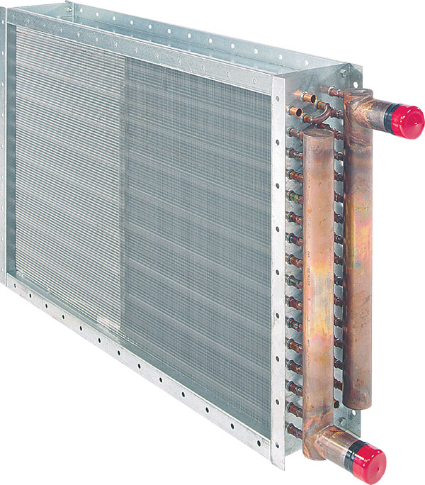
A typical chiller application might be used for comfort cooling in an office building or hotel. Each zone (or hotel room) would have its own hydronic finned tube coil heat exchanger (pictured below) as a means to transfer heat from the space to the secondary fluid. The flow of secondary fluid through the heat exchanger is controlled by a solenoid valve, which is energized/de-energized by a thermostat in the space.
One advantage to this design is the elimination of large refrigerant piping runs to each zone, with the tremendous amount of refrigerant which that would require. Instead, the refrigerant circuit is rather small, being contained within the piping circuit of the chiller only. This reduces the charge from potentially several thousand pounds to perhaps a hundred or so.
The secondary fluid for a chiller providing comfort cooling doesn’t require any measurable amount of glycol, as the application doesn’t have a significant chance of operating at refrigerant saturation temperatures below 32F. As such, the relative cost for the secondary fluid is very inexpensive compared to refrigerant.
Additionally, while there is a desire to eliminate the potentially environmentally damaging effects of refrigerant leaks, there is relatively little negative effect of a secondary fluid leak on a chiller.
In addition to comfort cooling, there are many commercial and industrial uses for chillers. The list is almost endless: bakeries, beverage bottling, breweries, dairies, food processing, fruit/vegetable washing, wineries, cement mixing, chemical plant processes, dry cleaning facilities, MRI testing, photo processing, plating processes, plastic injection molding, welding machines, and on.
Cool Books Conundrum
Now, let me share a specific chiller application that was used to provide a stable environment for the storage of antique books and papers. The requirements were maintaining a temperature between 65F to 68F, and relative humidity (RH) between 40% and 55%.
While this wouldn’t seem to be too difficult, for some reason the onsite chiller was not able to maintain a constant leaving fluid temperature, which made it impossible to maintain a space temperature that was anywhere near what was required. The contractor was at his wit’s end, and he was willing to experiment.
This is what was tried
The contractor used a discharge bypass valve to maintain a constant leaving secondary fluid temperature (see diagram below), but not just any discharge bypass valve. You see, mechanical pressure regulating valves used to maintain precise temperature control are at best challenged.
First of all, you have the shortcomings of a mechanical valve (spring and diaphragm hysteresis) which limits the valve’s ability to control precisely.
Secondly, a system is always at a disadvantage when attempting to control temperature by controlling some other parameter, such as pressure.
In addition to the pressure of the refrigerant in the evaporator, there are other factors that will influence the leaving fluid temperature (or the space temperature), such as load demand and ambient conditions.
Simply relying on a constant evaporator pressure (constant refrigeration saturation temperature in the evaporator) to ensure a constant leaving fluid temperature (or space temperature) will always be less reliable than actually controlling the temperature itself.
So, the decision was made to use an electronically-controlled electrical step -motor discharge bypass valve.
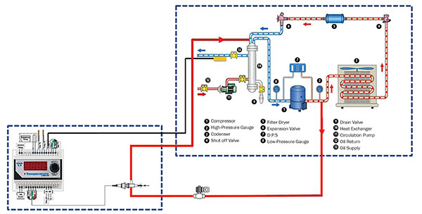
Now, this was a valve which would travel 6,386 steps from fully open to fully closed (at 200 steps per second), which gave it an amazing wide range of resolution. And, the valve was responding to temperature, not pressure. And specifically, the fluid outlet temperature of the heat exchanger.
In addition to the electric discharge bypass valve, a variable frequency drive (VFD) was utilized to vary the secondary fluid flowrate, which facilitated maintaining the space temperature.
This method of control was able to maintain the leaving fluid temperature at 42F, with a differential of +/- 0.75F conditioned space at temperature of 65F, with a differential of +/- 0.5F.
Boom….problem solved…now time to go get a chilled one and chill. <>

