
Circuit Purging – 30 Mechanical Minutes
January 23, 2023 | By Logan Caswell
John Siegenthaler shares the basics on getting the air out of modern closed-loop hydronic circuits.

HPAC editor Doug Picklyk (left) is joined by John Siegenthaler to discuss getting the water out of hydronic set ups.
The latest installment of HPAC magazine’s 30 Mechanical Minutes free webinar series focused on hydronic circuit purging, getting air out of closed-loop systems. In this episode, HPAC editor Doug Picklyk was joined by regular contributor and hydronics expert John Siegenthaler. This edition was sponsored by Wolseley Canada.
The introduction of air into hydronic circuits can be problematic and a source of frustration for industry professionals and end users. Careful attention to purging and following best practices will only improve the quality of work in the field.
According to Siegenthaler, systems are meant to operate air-free with just water. There are a few issues with air in a hydronic system. For example, corrosion due to oxygen in contact with ferrous metals, sound issues, inadequate flow rates (if there’s a mixture of air bubbles and water), and in some cases, air binding in systems that could prevent hot water from the heat source from reaching the heat emitter.
“Today’s systems make it easier to remove air so these problems don’t occur,” acknowledged Seigenthaler, who then described how old legacy methods of air removal often relied on air passively rising to high points in the system where a venting device would typically be located.
Newer technology, although now considered ‘traditional,’ for removing air from systems include the air bleeder valves located at a high point on the baseboard heater or panel radiator. These methods still rely on air passively rising to high points in the system where manual venting would be required.
He also described the ‘air scoop’, typically a cast iron device that creates a high point in the piping system and has internal baffles that help direct air bubbles up into a air vent that will burp the air out of the system. While these air removal systems are still available, he notes that they don’t work as well as modern micro-bubble separators.
“When you put cold water into a system, 3% to 4% of the H2O is made up of dissolved molecules of oxygen, nitrogen and carbon dioxide that cannot be seen,” explained Siegenthaler. It’s these molecules that form the micro bubbles in water that we’re trying to capture, the dissolved oxygen in particular. “When we de-aerate the system properly that oxygen content is of no concern.”
Today’s micro-bubble air separators have a central chamber where microbubbles will adhere to the surfaces of a coalescing medium—in effect the microbubbles cling to a surface and combine into larger bubbles and then rise upwards to a float-type vent where the air is automatically ejected.
Typically, these air separators are placed at high-temperature locations on the supply side of the boiler because as the water is heated the gas in the fluid will expand the gas molecules. “You can think of hot water going through an air separator almost like squeezing a sponge. You’re squeezing the dissolved air out of the water, capturing it and ejecting it from the system.”
Siegenthaler then spoke about forced air purging at start up and the use of a modern purging valve, installed in the circuit close to where the cold water will enter the system. He showed a photo of a purge valve (Figure 1) which includes an inline ball valve to stop the water flowing to the boiler, and a 90-degree side outlet port with a hose connection on it and a ball valve leading to that port.
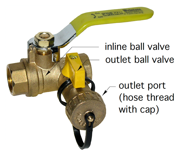
Figure 1. A modern purging valve for forced water purging.
In forced water purging the water entering a system, either for the first time or to refill, acts like a piston, pushing most of the air ahead of it. The incoming water must move at least two feet per second to be effective and preferable higher, suggests Siegenthaler.
In a schematic he shows the make-up cold water coming in first through a backflow preventer, then through an open bypass valve (or fast-fill) to allow the water to avoid a pressure reducing valve, then the water rushes through the boiler and the rest of the circuit, pushing the air out until the water flow reaches the purge valve which is closed to inline flow, and the outlet port is open with a hose connected and led to a large bucket or drain.
According to Siegenthaler, the forced water purging might remove over 95% of the air from the system, but the “clean up”, the removal of the dissolved air, is the function of the microbubble air separator.
He also presented schematics for a multi-zone piping configuration (figure 2) with purge valves located on the return side of each zone. To purge air from this system, you close off each zone’s isolation valves individually. Once one zone is purged and the water is released into the bucket, you close it and move on to the next zone, continuing through the entire circuit. He suggests this should only take a few minutes, providing you have good water pressure.
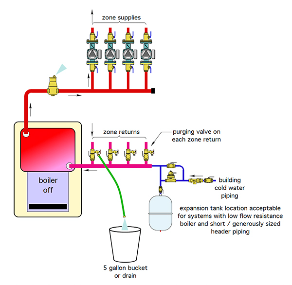
Figure 2. Schematic of a purging set-up for a multi-zone system.
In a primary/secondary system (figure 3), Siegenthaler shows a purge valve on the return side of each secondary circuit. He suggests against placing a ball valve in between the two closely-spaced tees leading to and away from the secondary circuit, as that valve is only useful for purging, that’s it. Plus it will create pressure drop between the two tees, and the concept of closely-spaced-tees is to get the pressure drop between them to as close to zero as possible.
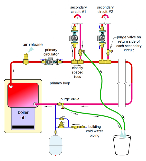
Figure 3. Set up for a primary/secondary circuit purging system.
Placing the purge valve on the return side of the secondary circuit allows the isolation of each circuit if you need repairs, and there is no pressure drop between the tees.
Typically, the process is to purge the primary first, and then work from one secondary to the next and so on through the different circuits.
Seigenthaler mentioned that systems with glycol should use a double-port purging valve (figure 4) with two 90-degree side ports with hose connections and a valve to close the flow between the two connections. Also, you don’t want to have automatic makeup water on a system like this because it would dilute the antifreeze concentration if there is a leak in the system.
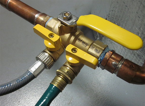
Figure 4. Example of a double-port purging valve set up.
To get a pre-mixed glycol solution into the system (figure 5), he recommends having the mixture in a bucket with a submersible pump, and pump the fluid into the system. Siegenthaler warns, “I learned this lesson the hard way: make sure you fasten that return hose into the container somehow, because with a strong pump that hose can take off like a deranged elephant’s trunk.”
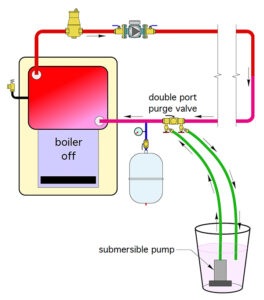
Figure 5. Example using a double-port purging valve to set up a glycol system.
Siegenthaler also shared some field experiences regarding air entrapment in systems. He notes that many small zone circulators come with a small spring-loaded check valve insert. When you install the circulator vertically, there is a potential for trapped air to accumulate under that check valve.
That air will tend to displace water in the vicinity of the circulator’s impeller; when that pump starts up, there is a mixture of air and water around the volute, and the impellor may not be able to ‘get a grip’ on that fluid.
To avoid this, he suggests a good forced air purge will get most of the bulk air out of the system, also that check valve could be removed from the circulator, and perhaps install a check valve a foot or two above the circulator, or install the circulator with horizontal or downward flow and that orientation change can prevent those air pockets from accumulating.
Also, when you start a circulator with cold water you may hear churning sounds from the circulator caused by gaseous cavitation—micro bubbles forming around the eye of the impeller. Siegenthaler suggests that his trapped air should be eliminated with good forced water purging when loading the system along with the installation of a modern micro bubble separator somewhere in the system.
Siegenthaler also addressed a number of viewer questions regarding issues like proper placement for air and dirt separators, positioning of expansion tanks and more.
To view this entire episode or to catch up on previous episodes of of 30 Mechanical Minutes head online and visit: hpacmag.com/tech-pulse or youtube.com/@hpacmag.
