
Is your client’s compressor ready for the summer heat?
May 28, 2019 | By Dave Demma
Other than the cost there are no serious arguments against performing preventive maintenance on air-conditioning and/or refrigeration equipment. And to the customers who would balk at paying a qualified technician to merely “maintain” their equipment, the only response to them is “You can either pay me a little to properly maintain your equipment, or you can pay me a lot more when it breaks down.”
However, as we get closer to summer, it is a good time to inspect those air conditioning and refrigeration systems and make sure they are prepared to deliver their rated capacity during elevated ambient conditions that are present during the summer months.
While there are several items on any thorough preventive maintenance checklist, the one I am focusing on today is cleaning condensers. Specifically, have the condensers been cleaned? This is essential for allowing condensers to operate at their rated capacity, which in turn will allow the compressor to operate at its rated capacity. It is a rather non-technical job, and some contractors will use their lower level apprentices or tradesmen to perform this task, but that does not diminish its importance.
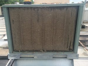
Figure 1 Dirty condenser due to lack of maintenance
A dirty condenser can lead to several debilitating conditions that can negatively affect equipment performance, and ultimately result in a reduced compressor lifespan. Figure 1 is a typical example of lack of maintenance, showing up as a dirty condenser.
The dirt accumulation on the condenser fins/tubes has a twofold negative impact. Dirt acts as an insulator, reducing the efficiency of the heat transfer process between the discharge vapour in the condenser and the air flowing through the condenser. Air flow through the condenser is also restricted by dirt.
The end result is a higher discharge pressure and temperature, which will result in a loss of lubrication film.
EFFECT ON LUBRICANTS
Refrigeration oils have been highly refined in an effort to elevate the temperature at which chemical decomposition will occur. As such, they are vulnerable to losing the lubrication film necessary to prevent metal to metal contact between bearings and journals, or piston rings and cylinders, prior to the temperature at which decomposition begins.
With mineral oil will this will occur approximately between 310F and 330F. When these temperatures are achieved, the probability of extreme piston and ring wear is imminent.
Chemical decomposition happens at elevated temperatures and is accelerated in the presence of other contaminants such as air or water. 18F is an important number to remember, for the rate of chemical reaction doubles with every 18F temperature increase. For example, a chemical reaction that takes 10 years to complete at 100F will only take five years to complete at 118F. At 136F it will be complete in two and a half years, and so on.
Mineral oil will start to decompose at approximately 350F (400F for POE oil). As temperatures increase above this threshold, the oil starts to polymerize. In plain English this means the molecules which constitute the oil’s makeup will start to combine into larger and larger molecules. First the oil transforms into a dark thick oil, then a sludge, and finally a solid powder.
The presence of oil breakdown in the refrigeration system can have many negative impacts. Sludge/solid particulate can plug up the oil inlet screen in the compressor sump, or the lubrication passages in the crankshaft. Each of these will have the same devastating consequence: loss of lubrication, and ultimately failed bearings.
COMPRESSOR CAPACITY
When selecting air-conditioning or refrigeration equipment for a specific application, the required capacity will be based on the anticipated heat load during the most extreme ambient condition the equipment will operate under in the summer months.
Let’s assume this is a meat packing plant and the equipment is situated in an area that will see a high of 105F during the summer months. The following factors will determine the heat load:
• Space temperature
• Product load
• Lighting load
• Evaporator fan motor load
• People/equipment load
• Air infiltration load
• Heat transmission load (dependent on type of insulation)
The heat load will be significantly higher during the 105F ambient condition than it will be during a 70F ambient condition in the springtime. As such, the equipment will be oversized during that season. In fact, the equipment will be oversized during any ambient condition lower than 105F. The fact is, the equipment will be selected based on the heat load during the most miserably hot days anticipated during the year.
So, what happens to compressor capacity as the discharge pressure increases? Reciprocating compressors, by design, have a built-in inefficiency. At the top of piston stroke, a clearance exists between the piston dome and the bottom of the valve plate, preventing any contact between the two. This is called the clearance volume.
Clearance volume is the source of the inefficiency, as it does not allow 100 per cent of the compressed vapour to flow into the discharge manifold. A pocket of vapour remains behind after every cylinder revolution. This trapped vapour is also at the discharge pressure.
Before any suction vapour can re-enter the cylinder for the next compression cycle, the clearance volume vapour must experience a reduction in pressure to a level slightly below that of the suction pressure. Otherwise, there would be no flow into the cylinder.
How does that reduction in pressure happen? There is an inversely proportional relationship between pressure and volume. When a quantity of vapour (contained in a defined volume, such as a piston cylinder), is increased or decreased, the vapour will respectively experience a decrease or increase in pressure.
Following a completed compression cycle, the piston proceeds to travel down, increasing the cylinder volume, and reducing the cylinder pressure low enough to draw refrigerant from the suction manifold into the cylinder. At the bottom of the piston stroke, the cylinder will contain its full volume of vapour.
As the piston starts to travel back up, reducing the volume of the cylinder, the vapour pressure increases. When the piston reaches the top of its stroke, the entire volume of compressed vapour will have exited the cylinder through the discharge valves except for the vapour trapped in the clearance volume.
It is piston travel, which increases cylinder volume, that reduces this clearance volume pressure. This portion of the piston travel, which is entirely dedicated to lowering the clearance volume pressure, performs no useful work at all. The higher the clearance volume pressure is above suction pressure, the more of this wasted piston travel will be required to reduce the cylinder volume to a point where suction vapour can enter the cylinder.
The “higher the clearance volume pressure is above the suction pressure” is a good layman’s definition for compression ratio.
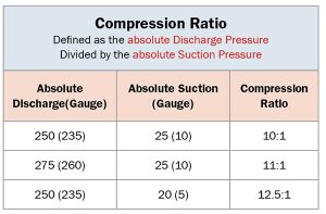
Figure 2
The technical definition is: the ratio of the absolute discharge pressure divided by the absolute suction pressure. It can be calculated as follows: Referring to Figure 2, we see a system operating at a discharge pressure of 235 psig and a suction pressure of 10 psig. These values must be converted to absolute pressure before the CR can be determined. This is done by adding atmospheric pressure to the gauge reading; 14.7 (rounding up to 15 for convenience) at sea level. This results in a discharge pressure of 250 psia, a suction pressure of 25 psia, and a compression ratio of 250/25, or 10:1.
The compression ratio can be reduced by lowering the discharge pressure, raising the suction pressure, or a combination of both. Figure 2 illustrates that raising the discharge pressure 25 psi, while maintaining the suction pressure at 10 psig (25 psia) will result in the CR increasing to 11:1.
Likewise maintaining the discharge pressure at 235 psig (250 psia), and lowering the suction pressure to 5 psig (20 psia) results in a more significant increase to the CR, at 12.5:1. It is important to realize that raising or lowering the suction pressure by some value will have a much greater affect on CR than raising or lowering the discharge pressure by the same value. Therefore, while it is important to keep the discharge pressure to a minimum without adversely affecting proper system operation, it is imperative that the suction pressure be maintained at the highest possible level.
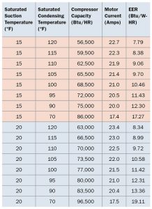
Figure 3 Changes to compressor capacity
And here is where the rubber meets the road. Figure 3 shows how the compressor capacity changes as the discharge pressure and/or suction pressure increases/decreases (increasing or decreasing the compression ratio). While this is a discussion about maintaining the condenser, it must be noted that systems operating at a suction pressure below the design condition will also experience an increased compression ratio and the resulting drop in capacity.
If you are in an area of the world where you will see an ambient temperature of 105F in the summer, and the condenser is selected based on a 15F TD, then the system will be operating at 120F condensing temperature in the summer.
Now, if the equipment is located in an area where the ambient high is 90F, but the condenser is in the same condition as shown in Figure 1, you may well be operating at 120F condensing with a net loss of 10,500 Btu (at a 20F SST). That is a 14 per cent loss in compressor capacity. This just might be the determining factor in whether the equipment is able to maintain the design temperature or not.
Considering the elevated oil temperatures which can cause oil decomposition, potential restriction of flow controls due to oil decomposition, loss of lubrication which can result in a failed compressor, and the loss of capacity (with the resulting loss in product sales, or even spoiled product), it should be an easy case to convince the equipment owner to budget the necessary expenditure to maintain their equipment.
But that may be asking a lot. <>
Dave Demma holds a degree in refrigeration engineering and worked as a journeyman refrigeration technician before moving into the manufacturing sector where he regularly trains contractor and engineering groups. He can be reached at ddemma@uri.com.
