
The effect of heating coil performance on boiler efficiency and system complexity
December 17, 2016 | By Robert Bean
Lately I have been noticing during reviews that designers are selecting fan/coils without regard to system efficiency and control simplicity. A few extra minutes of evaluation can add several efficiency points while eliminating the need for mixing strategies. Let’s start by stating all heat exchangers are based on a simple but very useful formula which looks like this: q = U * A * LMTD
where
q = thermal power transferred, Btu/hr, (W)
U = coefficient of heat transfer, Btu/hr/sf/°F (W/m2K)
A = surface area of the heat transfer component, ft2, (m2)
LMTD = log mean temperature difference between the hot and the cold medium, °F (K)
Both U and A are characteristics of the heat exchanger where U is determined by material properties, calculation and fabrication, and validated by testing; and A as required for output based on the LMTD.
The LMTD designated as “∆Tlm” is determined by the following formula (i,ii):![]()
Where for heating coils,![]()
And as configured for counter flow shown in Figure 1.
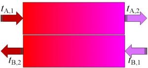
Where tA,1=entering fluid temperature; tA,2=leaving fluid temperature; tB,1=entering air temperature; and tB,2=leaving air temperature.
Now put down the magazine and go to your favorite flavour of fan/coil brochure and try to locate all of the assumed temperature inlet/outlet values that led to the model you might be selecting for your next application. Have you come back scratching your head? I will bet yes since only a few manufacturers will provide the necessary details for detailed application evaluations. As you will soon see it is not just a simple matter of selecting a model that “looks like it will do the job” from a manufacturer’s catalogue, certainly not if you want to simplify controls and optimize for boiler efficiency.
Two lessons
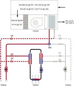
Figure 2
Never assume the manufacturer’s fan/coil performance data is a match for your project just because of the published capacities. Always assume you can optimize the selection with a little work and help from the manufacturer (I will likely take heat for writing this–pun intended–but that is why manufacturers employ engineers).
To illustrate how improper selection can affect system efficiency and control complexity I have taken a common application for a hybrid heating system as shown in Figure 2 where a boiler is serving a fan/coil and radiant floor system.
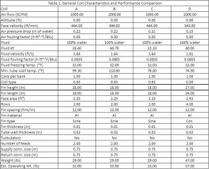
Table 1
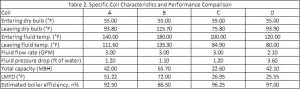
Table 2
Then I compared four coils; three were identical models (A, B and C) and one (D) was slightly modified and upsized in surface area. Then I fixed the fluid and airflow and entering mixed air temperature so entering air conditions were equal for all four coils. The performance results are summarized in Table 1 and for clarity I have presented the more critical points in Table 2.
Comments
Notice the completely different performance capacities for the three identical coils A, B and C based on the relationships between entering/leaving fluid temperatures and entering/leaving air temperatures, see Figures 3 and 4.
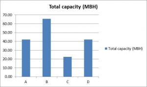
Figure 3 Coil capacities. A, B and C are identical models. D is modified and upsized.
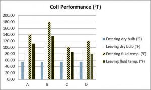
Figure 4 Coil performances. A, B and C are identical models. D is modified and upsized.
Now let’s take an example of a transitional home, one where loads are between 10 Btu/hr/ft2 and 20 Btu/h/ft2 (32 W/m2 and 63 W/m2).iii If it is necessary for you to select a fan/coil for its mid capacity (Coil A) to maximum capacity (Coil B) you will have to introduce mixing controls for the radiant system simply because the desired leaving air temperature is going to require higher entering fluid temperatures (>140F (>60C))– higher than typically required for the floor heating (showing the two-way injection method in Figure 2). Note also the return fluid temperatures and their effect on boiler efficiency as shown in Figure 5.
Big message: “looks like it should work” selections by designers can unnecessarily add control cost and complexity and destroy boiler efficiency at peak loads.
With regards to Coil C; a discharge temperature close to ambient (75.8F (24.3C), Figure 4) is not going to be sufficient for space heating at -30F (-34C) peak loads in a transitional building, especially if the duct design and register selection results in high air velocities around the occupants.
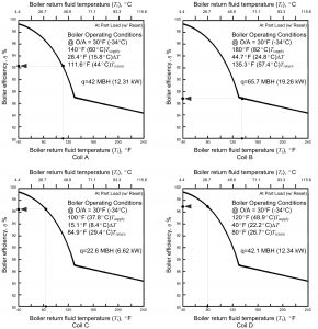
Figure 5 Condensing boiler efficiency for four coils. A, B and C are identical models. D is modified and upsized. Ref.: ASHRAE HVAC Systems & Equipment Handbook, Chpt 32, Figure 6
How can you achieve capacity and comfort without having to resort to higher temperatures and mixing controls and still enable the boiler to achieve its maximum rated efficiency? Enter coil D. Coil D has a slightly larger face area (2.92 ft2 versus 2.25 ft2 (0.27m2 vs. 0.21m2), two more rows (four versus two), corrugated fin pattern versus sine-wave fin pattern and built with smaller diameter tubes (1/2” versus 5/8” (12.7mm vs. 16mm)). Due to the larger coil surface area the face velocity is lower (343 fpm versus 444 fpm (1.74m/s versus 2.26m/s)) resulting in less pressure drop (0.15 in H2O versus 0.21 in H2O (37Pa versus 52Pa)). Note that it has a similar discharge air temperature as Coil A (93F (34C)) and similar capacity (42 MBH (12.4kW)) but uses a lower entering (120F versus 140F (49C versus 60C)) and leaving fluid temperature (80F versus 116.6F (27C versus 47C)). It requires less flow (two gpm versus three gpm (0.13l/s versus 0.19l/s) and yet has higher velocity (1.81 fps versus 1.64 fps (0.56m/s versus 0.50m/s) – all good things.
The down side is an unremarkable increase in pressure drop (3.6 ft hd versus 1.2 ft hd (11kPa versus 3.6kPa) and one time capital cost increase due to the coil configurationiv. But with a lower design fluid temperature the extra cost for the coil could easily be offset by the elimination of a mixing system. This simplifies the system and results in a lifetime increase in boiler efficiency, especially at the higher loads. This is not the whole picture because I have not dissected the building performance for compliance with ASHRAE Standard 55, and the duct and register design for compliance with the ADPI, but you get the idea of what is possible with a little bit of work. I have also left out the challenges of product configurations and manufacturers offering standardized catalogue items.
SHORT STROKES
With proper selection, reset on the boiler and a lower common system temperature will make the hybrid sing like it should with less control headaches; and you will future-proof the system for low temperature heat sources more aligned with renewables and the philosophies of sustainability.
Robert Bean, who is president of Indoor Climate Consultants Inc., is a Registered Engineering Technologist in building construction through the Association of Science and Engineering Technology Professionals of Alberta and a Professional Licensee in mechanical engineering through the Association of Professional Engineers, Geologists and Geophysicists of Alberta. He has served two terms as an ASHRAE distinguished lecturer, serves on ASHRAE committees TC 6.1 (Hydronics), TC 6.5 (Radiant), TC 7.4 (Exergy) and SSPC 55 (Thermal Comfort) and is a recipient of ASHRAE’s Lou Flagg Award.

