
Flow Energy … Don’t Waste It
March 25, 2021 | By John Siegenthaler
Taking steps to streamline and optimize the flow within a hydronic design contributes to the system’s overall efficiency.
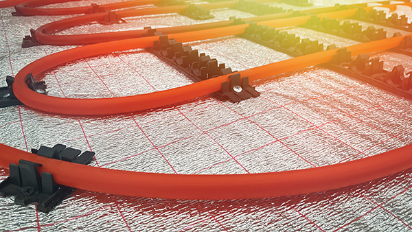
Getty Images
Ask most heating professionals about the energy used by the systems they design or install, and the responses are almost guaranteed to deal with “fuel“ energy (e.g., natural, gas, propane, oil, pellets, etc.) required by their systems.
With the exception of systems using electric boilers or heat pumps as their primary heat source, few heating pros give much thought to the electrical energy used in their systems. Perhaps they view such energy as trivial in comparison to fuel energy. They might regard it as simply a “parasitic” necessity for delivering heat produced by the high-efficiency heat sources they install.
That mindset has a historical parallel in the auto industry. Think back to what automobiles looked like in the mid-twentieth century. Many had large exterior “appurtenances” such as out-swinging vent windows, flat-facing mirrors, hood ornaments, chrome trim, massive front ends, and other objects that were part of the auto persona of that time. A 1956 Cadillac Fleetwood weighed more than 5,000 lbs., about the same as a new F-150 pickup. That Cadillac also got about 10.5 miles per gallon.
In that era fuel was relatively cheap and seemingly endless in supply. There wasn’t much concern for increasing mileage by streamlining cars. Those V8 engines with 4-barrel carburetors had the power to overcome the drag. One of the most recognized auto designers of that era, Enzo Ferrari, expressed it well: “Aerodynamics are for people who can’t build engines.”
Today’s cars are very different. Many have streamlined bodies designed to minimize drag. Nearly all are significantly lighter than those of the mid-twentieth century. These details are all aimed at increasing fuel mileage.
So why all the discussion of old automobiles? It’s because today’s hydronics industry, at times, seems to treat the energy used to move heat from where it’s generated to where it’s needed in the building with the same attitude of the mid-twentieth-century car designer. If the heat isn’t moving along fast enough, or the flow path has high resistance, just use a larger circulator.
Simple Multiplication
Every component that has fluid passing through it dissipates head (mechanical energy) from that fluid. The amount of mechanical power required to push flow through a component, or a string of components in a series, can be calculated using the following formula.
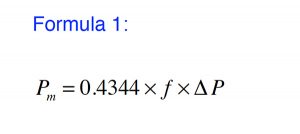
Where:
- Pm = mechanical power dissipated (watts)
- 0.4344 = a constant required by the units in the formula
- f = flow rate (gallons/minute)
- ∆P = pressure drop through the component(s) (psi)
The higher the flow rate, and the higher the pressure drop, the greater the mechanical power dissipated. Here’s an example:
How much mechanical power will be required to move 120F water at 10 gpm through 120 feet. of 1-in. type M copper pipe? The flow rate is stated, but not the pressure drop. To get that pressure drop you can turn to several sources—tables, formulas, or software.
I like to use the Hydronics Design Studio software for such calculations because it accurately accounts for the changes in fluid properties based on temperature, which in turn effects pressure drop. Putting the stated numbers into the software yields a pressure drop of 2.4 psi. The remaining math is easy:
![]()
Although the units on the result are in watts, and most of us associate watts with electricity, understand that this is not the electrical input power required to sustain the stated conditions. It’s the mechanical output power required by the circulator.
We pay for the electrical power input to the circulator, not the output power. To calculate the input power we would need to know the wire-to-water efficiency of the circulator creating this condition.
The efficiency is very dependent on where the circulator is operating on its pump curve. Ideally, the circulator is operating near the middle of its pump curve, where the wire to water efficiency is highest.
If we assume a small circulator with a PSC (permanent split capacitor) motor is operating under favorable conditions (e.g., near the centre of its pump curve), a reasonable value for wire-to-water efficiency is 20 to 25%. Let’s split the difference and assume 22.5%.
To calculate the electrical input power to the circulator in our example, divide the mechanical output power (which we determined to be 10.4 watts) by the wire-to-water efficiency of the circulator, as shown in formula 2.
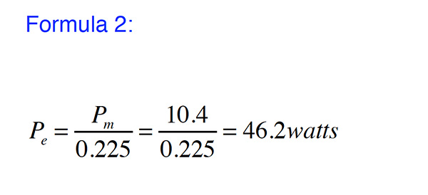
We’ll use this value as a baseline for comparison.
Do “Substitutions” Matter?
How about if we used 1-in. PEX tubing instead of 1-in. type M copper tubing for this segment of the system, and we change the circulator, if necessary, to ensure that the same 10 gpm flow is achieved?
Changing the pipe changes the pressure drop. The Hydronics Design Studio software quickly returns a pressure drop of 6.24 psi for 120 feet of 1-in. PEX operating with water at 120F and 10 gpm.
This change pushes the mechanical power requirement to 27.1 watts, and the circulator input power (assuming the same 22.5% wire-to-water efficiency) to 120 watts. That’s a significant increase in pumping power. It’s the result of the smaller internal diameter of 1-in. PEX (0.875-in.) versus that of 1-in. type M copper (1.055-in.).
You might be thinking I made up this example to dissuade you from using PEX rather than copper for distribution piping. Not so. Instead, I’m trying to show that what might seem like an “equivalent” substitute (1-in. PEX for 1-in. copper) can have ramifications. In this case it adds significant operating cost over the life of the system.
If we assume that flow passes through this 120 feet of pipe for an average of 3,000 hours per year, and that the electrical energy costs $0.15 per kWh, and that electrical energy costs escalate at 2% per year. The difference in operating cost over 20 years would be $807! That’s just for this 120 feet of 1-in. piping. You won’t pay it, but your customer will.
Moving Forward
If you design, install or manufacture hardware for hydronic systems you should be continually thinking about ways to reduce the electrical operating cost of those systems.
Our industry should embrace ways to reduce circulator count. One example would be eliminating “dedicated” primary loop circulators. Those that only push flow through the primary loop, and not the heat source or any load circuits.
Another approach would be using (or creating) heat sources that don’t have high head loss heat exchangers, and thus conserve head energy. In my opinion, a “self-buffering” heat source with very low head loss is ideal. It eliminates the need for a buffer tank as well as a circulator between that tank and the heat source.
This approach is likely to cost less (materials and labour) and install faster than using a heat source combined with a separate buffer tank and all the piping, fittings, valves, and circulator between them.
The use of variable speed circulators with integral speed control algorithms used in combination with valve-based zoning rather than dedicated zone circulators is another way to reduce the power demand of distribution systems.
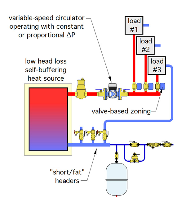
Figure 1. DO THIS
Figures 1 (above) and 2 (below) show several of these concepts.
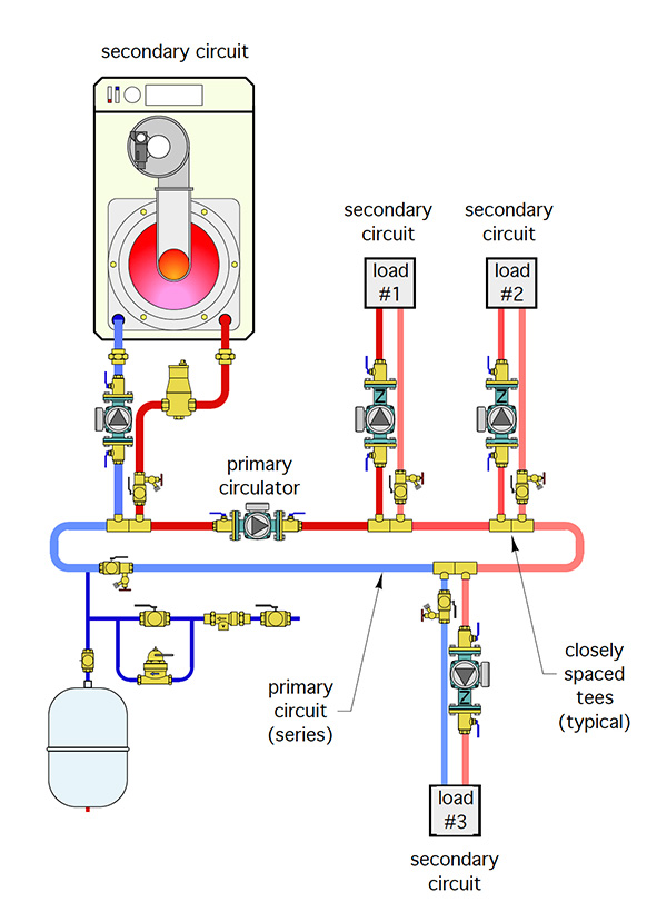
Figure 2. NOT THIS
We should avoid using excessively oversized circulators and then throttling away their excess head with balancing valves. That’s analogous to driving a car around with the gas pedal pressed down farther than necessary and controlling speed with partially applied brakes.
We should use dirt separators that don’t increase their pressure drop as internal screens load up.
We should use glycol-based antifreeze “judiciously.” The higher the concentration of glycol, the higher the density and viscosity of the solution, and the higher the ratio of viscosity divided by density is, the greater the “drag” as fluid passes through the system.<
If your piping layout requires a lot of 90-degree turns, consider using a tube bender to create larger radius bends rather than
using standard 90-degree elbows. Larger radius bends decrease turbulence and thus decrease head energy dissipation.
We should also take a close look at heat emitters such as panel radiators, which can operate with design load ∆Ts in the range of 30-36F rather than 20 F. The higher the ∆T the lower the required flow rate, and thus the lower the head loss for a given pipe size.
We should compare the added cost of using one size larger piping, and thus reduced head loss, against the life-cycle electrical energy savings associated with a smaller circulator.
The science of fluid dynamics has been extensively applied in many technologies where a fluid moves across a surface. Compare the planes, cars and boats from the middle of last century to those of today. The shapes are very different, and the reduction in energy use due to decreased drag has been remarkable.
If our charge as hydronic professionals is to improve the overall energy efficiency of the methods and materials we assemble, we shouldn’t treat the electrical energy used by our distribution systems is trivial. Energy, as fuel or embodied in flow (e.g., head), is a terrible thing to waste! <>
 John Siegenthaler, P.E., is a mechanical engineering graduate of Rensselaer Polytechnic Institute and a licensed professional engineer. He has more than 40 years experience in designing modern hydronic heating systems. Siegenthaler’s latest book is Heating with Renewable Energy (see www.hydronicpros.com for more information).