
Get Your Motor Runnin’
June 19, 2020 | By Curtis Bennett
An inside look at what’s driving your pumps and more.
(Getty Images)
If this article’s headline gets you singing the next line to that song, well then you’re a classic rocker, but we are not here to talk about rock and roll, it’s motors that are on the agenda today.
Pumps are the heart of a hydronic heating system, and at the heart of every pump there is a motor.
In our industry the pump is the most widely used example of motors, and pumps have not been immune from the push to become more efficient.
Every watt counts now, where it’s used, how efficient it is, and how efficient the entire system is. I am glad to see more efficient pumps because I have seen more systems with pumps that are too big than pumps that are too small.
This leads not only to electrical inefficiency, but system inefficiency. But that’s a topic I will leave for Siggy (regular HPAC contributor and hydronics specialist John Siegenthaler).
My first job out of school was working on automotive repair equipment. Getting a job today is nothing like back then. I remember calling every listing in the Yellow Pages under “Electronics” until finally someone bit the hook.
I was literally thrown to the wolves to start fixing and refurbishing some of this equipment. For example, I was working on a very big wheel balancer for semi-truck tires. Well you guessed it, the motor used to turn the big truck tires was huge. No 120VAC motor in this one. It was 460VAC, and I was a rookie.
If I remember correctly, I was tensioning a spring or prying something inside of the unit, and yes I did not unplug it because I did not think I would get shocked. Well, if you have read any of my other articles, you know what happens next. Wrong, I didn’t get shocked, because I was hanging onto the screwdriver handle, and plastic makes a very good insulator.
For once Lady Luck was on my side. I was insulated, but the light show that happened inside was amazing. Sparks flew everywhere. Now don’t get me wrong, I am not making light of my stupidity, but it does make for a good story. The moral of this one, like all the others, is disconnect the power before servicing.
So back to the basics. Since the dawn of time AC motors have been used in mechanical systems, so let’s just dive right in on how the inductive AC motor works.
If you remember my article on transformers you may recall how awesome transformers are because they convert energy without the parts being connected together by wires. Well the inductive motor does the same thing, except it turns a rotor while doing it. It’s actually crazy how electricity works, and moreover how induction works.
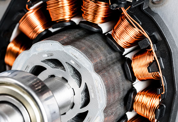
So there are “basically” two parts to an inductive motor. You have the stator, the part that has the electricity attached to it, and you have the rotor, the part that rotates inside the motor.
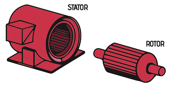
The basic elements of an inductive AC motor.
The coolest part about induction is that it works without wires. Have I said that before? Like the transformer, it transfers energy to another part without being connected.
For our example, let’s say the stator is connected to 120VAC single phase (a refresher: as we have talked about before 120VAC is a voltage that swings positive and negative at a rate of 60 times per second or 60Hz). It’s alternating above and below “Zero volts”. This is where the term AC comes from.
So this AC voltage goes into the stator, which is just a bunch of copper windings, yes you guessed it, just like the transformer, where when you put voltage and current into wound up wire you get an awesome thing: an electromagnetic field.
The rotor is usually made up of magnetic parts that are opposite charges, South and North. These magnets run lengthwise in the rotor all the way around. There are a bunch of them, and they alternate North Pole and South Pole. Remember learning about magnets in grade three? North and North repel each other, and North and South attract. So the stator, like the transformer, sends out an electromagnetic field.
The difference between a motor and a transformer, except for the obvious, is that a motor has multiple windings. It could have more than two sets, but for now we will just say two sets. It needs more than one because in the case of a motor the windings are not all working at the same time. Electricity is flowing only to one set at a time and this is how it pushes the rotor around.
We have all used, or at least seen, those little pump checker fobs, the one where the little wheel spins when you hold it on the front of the pump. That is not actually telling you that the rotor is spinning, that’s only telling you that the stator windings are working properly, producing an electromagnetic field.
It’s the electromagnetic field that is turning the little wheel inside the fob. That is exactly how the stator turns the rotor in the motor.
Think of it like this, you have a merry-go-round with two handles on opposite sides for pushing it around. Now you have four people pushing it, they are standing at 12:00, 3:00, 6:00 and 9:00. Remember there are only two handles for pushing, so only two people can be pushing the merry-go-round at a time, either the guys at 12:00 and 6:00 or the guys at 9:00 and 3:00. That is how you get the merry-go-round spinning the fastest, one pair of “pushers” pushes, and then the next pair and so on and so on.
Well, I need to throw a little wrench into this analogy, because we are working with magnetics, the pushers that are not pushing are reaching out their arms as far as they can to pull the handles towards them when they get close. Remember that we are working with magnetism, so some parts repel and some parts attract.
I don’t want to complicate it any more, so we will just leave it there, with a tiny bit of mystery.
So the pushers are the stator and the merry-go-round is the rotor. In the case of a pump, the rotor is attached to the impeller that pushes the water inside the volute.
I want to touch on another aspect about inductive motors, other than the fact there are lots of them. You have probably looked inside the electrical box on the side of the pump and seen that little cylinder thingy. Well that’s a capacitor, and it helps to start the motor from a dead stop.
The capacitor is another cool electrical device that someday we may get into but not now.
OK, so I embellished a bit indicating that motors have only one stator but, single phase inductive motors can’t start up on their own, they need a little push from inside. This little pusher is a second smaller stator that in conjunction with the capacitor, puts the stator “out of phase” with the rotor to start it up.
It’s essentially another “pusher” on the merry-go-round at 1:00 on the outside that once the merry-go-round starts he does not have to work anymore. The other guys do all the pushing.
I’ll go out on a limb and say most pumps in our industry are this type. Not the huge pumps, but up until about ½ HP, above ½ HP they usually go to a 3-phase motor, used in much bigger systems. We are not going to cover 3-phase motors because I wanted to hit on the “circulator” this time.
That should give you a little more insight into how an actual inductive motor works. I hope the oversimplification was not too much, but that it did help you to understand.
My intention is always to show, in the simplest way, how something electrical works, and I feel that breaking it down makes it a little more understandable.
Now bring in the smart people that want to change the world. The people who invented the ECM motor—the electrically commutated motor. That explanation will come in the next article. <>
Curtis Bennett C.E.T is product development manager with HBX Control Systems Inc. in Calgary. He formed HBX Control Systems with Tom Hermann in 2002. Its control systems are designed, engineered and manufactured in Canada to accommodate a range of hydronic heating and cooling needs commonly found in residential, commercial and industrial design applications.

