
How to select heat transfer surfaces
August 26, 2019 | By Dave Demma
There are many textbook definitions for the term refrigeration, but one of the most straight forward and easy to understand definitions is as follows: “the achievement of a temperature below that of the immediate surroundings.” In this article, when the term “refrigeration” is used, it is in reference to the process whereby the temperature in the “refrigerated space” is reduced below that of the immediate surroundings, regardless of what the ultimate temperature in the refrigerated space might be. In other words, we are discussing the process, and not a specific temperature application, meaning it applies to refrigeration, air conditioning, or any temperature application utilizing the vapour compression cycle as a means of providing “a temperature below that of the immediate surroundings.”
A QUESTION OF SEMANTICS
While it is very common for the refrigeration process to simply be referred to as “cooling,” it is more accurately described as a heat transfer process. The “achievement of a temperature below that of the immediate surroundings” is accomplished when heat is transferred out of the refrigerated space, which then results in a lower (or cooler) temperature. While it is probably somewhat elementary, as the term “heat transfer” implies, the heat is only transferred from the refrigerated space, it does not disappear. It is simply moved from one place to another.
The vapour compression cycle is the perfect vehicle to facilitate this heat transfer process, with the refrigerant being the medium that either absorbs (removes heat from the refrigerated space) heat, or rejects (adds heat to a different space or medium) heat.
The vapour compression system for a given application can be quite elaborate, with elaborate controls and special components and accessories. However, each system has the same four major components, each with its own specific (and rather simplistic) function. The desired result of each system is the same; to provide saturated refrigerant at a temperature below that of the refrigerated space, facilitating the heat transfer from the higher temperature air in the space to the lower temperature refrigerant.
1 Compressor: A vapour pump, which receives low pressure vapour and compresses it into a high pressure vapour. The mechanical process of compression adds heat to the vapour, so the discharge vapour leaving the compressor always exits at a higher pressure and at a temperature above saturation (superheated).
2 Condenser: This is one of two heat transfer surfaces present in the system, and its function is to transfer heat from the refrigerant to the atmosphere (in an air cooled condenser) or a secondary heat transfer fluid (water cooled condenser). In a properly-sized condenser, this will allow the vapour to be transformed from a superheated vapour, to a saturated vapour (desuperheated), then from a saturated vapour to a saturated liquid (change of state), then from a saturated liquid to a subcooled liquid.
3 Expansion Device: Again, the end goal of the system is to provide a saturated refrigerant at a temperature lower than the refrigerated space, so that heat in the space can be transferred to it. As such, the function of the expansion device is to allow for a reduction in liquid refrigerant pressure to a pressure that corresponds to the particular refrigerant saturation temperature required for the application.
4 Evaporator: This is the other heat transfer surface present in the system, and its function is to transfer heat from the refrigerated space to the saturated refrigerant flowing through the evaporator. Since the latent heat of vaporization (amount of heat required for a liquid to undergo a change of state to a vapour) is quite high, the majority of the evaporator will have saturated liquid flowing through it to allow for efficient heat transfer. The expansion device will regulate the flow of refrigerant into the evaporator, and maintain a minimum amount of superheat at the evaporator outlet… solely to prevent liquid refrigerant from flowing back to the compressor, and the resulting compressor damage that it would cause.
With it being established that refrigeration is a heat transfer process, and that there are two heat transfer surfaces present in the vapour compression cycle, how does one go about properly selecting those heat transfer surfaces (evaporator and condenser) for a specific application?
Evaporator
Let’s discuss the evaporator first. Its capacity is based upon the following:
• Physical size of the evaporator
• Temperature Difference (TD) between the air entering the evaporator, and the saturation temperature of the refrigerant flowing through the evaporator.
• Refrigerant type
• Evaporator refrigerant saturation temperature
• Fin spacing (number of fins/inch)
Altitude – The ability to transfer heat from the air in the refrigerated space to the saturated refrigerant flowing through the evaporator will in part depend on the mass of heat transfer medium (air) that is flowing through the fin-tube surface of the evaporator. Evaporator ratings are based on the air density (lbs/cu ft) at sea level. Air density decreases as altitude increases. With that decrease in density, the evaporator fans will still deliver the same CFM, but the “mass” of this heat transfer medium will be reduced, meaning the ability to transfer heat will be reduced. The chart in Table 1 shows the capacity de-rating based on altitude.
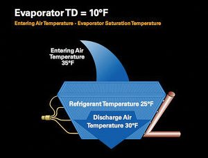
Figure 1 Evaporator TD
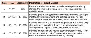
Table 1 RH Classes for refrigeration appliances
Figure 1 illustrates Evaporator TD; the air from the refrigerated space enters the evaporator fin-tube sheet at 40F. The saturation temperature of the refrigerant flowing through the evaporator is 25F. The TD is 15F (40F – 25F).
Evaporator TD is important for a couple of reasons.
It has a significant (and directly proportional) impact on evaporator capacity. For example, consider an evaporator rated at 12,000 Btu at a 10F TD. Double the TD to 20F, and you’ll double the capacity to 24,000 Btu.
The greater the Evaporator TD, the greater the amount of moisture content removal from the air. In products such as fresh meat, produce or floral, the system design should be such that the refrigeration system does not remove excessive amounts of moisture content from air, as this will result in the removal of moisture content from the refrigerated product. This will dry/damage the product, and will lessen its weight (lowering revenue of items that are sold by the kg./lb). The greater the TD, the greater the moisture content removed from the product.
As stated above, some products require an environment where the relative humidity is kept at higher levels. However, not all products require such a stringent level of relative humidity. Table 1 shows the various classes of TD/Relative Humidity for refrigeration applications.
While a high TD is not generally recommended for refrigerated storage, it is desirable in air conditioning applications. It is not uncommon to see a 35F TD in air conditioning applications, which will reduce the moisture content of the circulated air, providing a more comfortable environment.
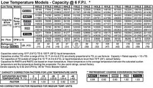
Table 2 Low temperature evaporator capacity
The standard rating point for the low temperature evaporators in Table 2 is a -20F saturated refrigerant temperature. Note that for a given evaporator model, there are varying Btu capacity ratings listed, based on the refrigerant type. For example, the 065LE is rated at 59,160 Btu with R-407A, and 61090 Btu for R-407C.
In addition, there are various capacity correction factors listed for refrigerant saturation temperatures from -40F to 0F.
This particular capacity chart is for evaporator models with six fins per inch. There are some low temperature applications where it would be advisable to use four fins per inch, so that as ice/frost starts to build up on the fins, it would allow more time before that buildup was excessive enough to require a defrost cycle. The model 55VE is the same cabinet size, same length and diameter tubing, same fan motors and fans, but is equipped with four fins per inch. The lower amount of fins per inch results in a reduction in capacity. In this case, the capacity drops to 50,600 Btu (not shown in the chart below).
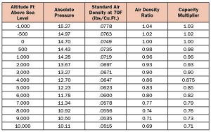
Table 3 Altitude evaporator de-rating
Table 3 shows the capacity reduction based on altitude. For example, the altitude in Denver, CO is 5,280 feet above sea level. For convenience sake, we’ll round that down to 5,000 feet. Based on the chart in Table 2, that means that the evaporator capacity will be reduced by 15 per cent. It is important to take this capacity de-rating when selecting equipment, so as to (1) ensure that there is sufficient evaporator capacity, and (2) maintain the correct capacity balance between the evaporator(s) and the condensing unit.
Condenser
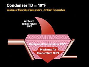
Figure 2 Condernser TD
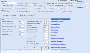
Figure 5
Considering the other heat transfer surface – the condenser – TD also plays a major role in the equipment selection. In Figure 2, the ambient air enters the condenser fin-tube sheet at 95F. The saturation temperature of the refrigerant flowing through the condenser is 105F. The TD is 10F (105F – 95F).
Similar to evaporator capacity, the condenser TD is directly proportional to condenser capacity.
This is illustrated in the condenser capacity chart shown in Table 4:
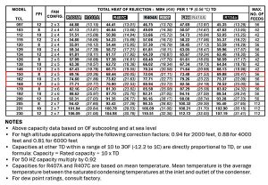 The capacity for the TCL162, using R-407A, has a capacity of 74.60 MBH. As the chart states, that capacity is per 1F TD. So, if this condenser was applied with a 10F TD, the condenser capacity would be 74.60 MBH x 10 = 746.0 MBH.
This presents a decision regarding the balance between system efficiency, and initial equipment cost. If the application required a condenser capacity of 1,800 MBH, this could be achieved utilizing the TCL162, with a 25F TD. That certainly will be the “low bid” condenser choice for this application.
However; there are several negative impacts in selecting the low bid condenser:
• The higher condensing temperature/condensing pressure will result in a reduced refrigeration effect,
• Higher discharge temperature, which will accelerate the rate at which oil will decompose,
• Higher compressor compression ratio, which will reduce compressor capacity.
But hey, you did save a few dollars.
As the chart reflects, there are slight differences in capacity of a given condenser model depending on the type of refrigerant being used.
In addition, various motor speeds are available for a given condenser footprint. Higher motor speeds will yield higher capacity with a given condenser footprint. But the higher fan speed will result in higher noise levels, which can be a concern in some applications.
Now, models TCL150, TCL162 and TCL168 all utilize the same cabinet size, the same length/diameter of tubing, the same fans/fan motors. The only difference between the three models is the fin spacing (fins/inch). Reducing fin spacing reduces the total heat transfer surface, which reduces condenser capacity.
There is a balance here…increasing fin spacing allows for more capacity out of a given condenser footprint. But, at some point the increased fin spacing will result in a condenser that is more susceptible to restrictions in airflow, caused by debris in the air. Some energy regulations are now calling for a minimum 10 fins per inch, to maintain a minimum condenser efficiency.
Again, we see that there is a capacity de-rating when the condenser is used in applications in higher than sea level altitudes. This is for the same reason stated above in relation to evaporator de-rating…the less dense air at higher altitudes reduces the mass of air flowing through the fin-tube surface, reducing the ability to transfer heat.
There is one final consideration in condenser selection. If the application requiring a condenser is utilizing six – 6DE3F11ME-TSK compressors (with a combined capacity of 669 MBH) selecting the TCL162, if the job specification required a 10F TD, (with a capacity of 746.0 MBH) would result in a condenser that was undersized.
Why is that?
The answer is “heat of compression”. There is a specific amount of heat added to the refrigerant during the compression process. So, the condenser selection will be based on the sum of the system capacity plus the heat of compression.
Looking at the compressor specifications in Table 3, the 6DE3F11ME-TSK has a capacity of 111.5 MBH, but a compressor heat of rejection of 176.86 MBH. So, the required condenser capacity will be 6 x 176.859 MBH = 1060.15 MBH.
Selecting the TCL162 in this application would require operating at a 15F TD. Or, to meet the required 10F TD specification is required, a larger condenser would need to be selected.
There are many considerations involved in evaporator and condenser selection, which makes sense given the importance of the vapour compression cycle in refrigeration, whatever the application. Knowing and understanding them will ensure the systems function effectively. <>
Dave Demma holds a degree in refrigeration engineering and worked as a journeyman refrigeration technician before moving into the manufacturing sector where he regularly trains contractor and engineering groups. He can be reached at ddemma@uri.com.
Tables 2,4 courtesy Trenton Refrigeration
Tables 1,3 courtesy Heatcraft
