
Integrated Design
March 2, 2020 | By Robert Bean
A case study in achieving IEQ and efficiency with human factor.

Figure 1: Conservative and practical architecture offers long-term resiliency and simplified control over noise, thermal transfer, air and light. Note the landscaping and foundation drainage plane to mitigate moisture issue and the low window-to-wall ratio to control sound, light, solar gains and radiant asymmetry and drafts.
I was recently in Vancouver participating as a guest speaker at an integrated design process (IDP) workshop held at the British Columbia Institute of Technology (BCIT) High Performance Building Lab. The event was a collaboration of BC Housing with BC Hydro, FortisBC and the Province of BC. The day-long function was facilitated by Andy Oding from Building Knowledge Canada and Gary Hamer from BC Hydro.
There is no single right or wrong definition of an of an IDP, and for the purposes of the workshop BC Housing’s Wilma Leung identified the group’s objectives as:
- Describe, test, and refine an IDP that can be used to optimize the design of a home that will serve occupants for 100-200 years;
- Describe the attributes of a home that is built to serve the needs of the occupants—including comfort, health and safety;
- Agree upon the essential participants needed for a design charrette (IDP professionals) and the role of the engineer/architect in leading the builder’s team process to deliver high performance/net zero homes.
I have worked on integrated design teams on many projects and see the process much like a business planning process I have used for years: It begins by identifying the business’s compass (the geography of the playing field and its sense of direction). Then you identify its purpose (why does it exist?), supported by a collections of visions (the pieces of the puzzle that must be achieved in order to fulfill the purpose). Those visions are achieved by a combination of executed strategies (the “what” that needs to happen to make the visions a reality) and tactics (the “work” required to complete the strategy) and goals (the “when” for the time-driven tactics). It is an integrated business planning method that is transparent, easy to understand and it works; and as I’ve discovered, it applies to the design and construction of buildings.
I have written before about the evils of the traditional design process where the architect/builder/owner segregates the project professionals.1 With the IDP it is all about integrating knowledge through the collaboration of the experts.
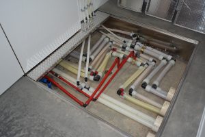
Figure 2: PEXa piping vaults in each unit supply heating, cooling and domestic hot and cold water (expansion loops shown).
The differences are important. In the traditional method the building design is typically based on compliance with the minimum requirements of mandatory codes written for safety and reducing the risk of illness. However, with an IDP (in my experience) it adopts human based indoor environmental quality (IEQ) standards and philosophies around sustainability and earth stewardship. As noted by Pearl (2004), “In professional practice, IDP has a significant impact on the makeup and role-playing of the initial design team. The client takes a more active role than usual, the architect becomes a team leader rather than the sole form-giver, and the structural, mechanical and electrical engineers take on active roles at early design stages. The team includes an energy specialist (simulator) and hopefully, a bio-climatic engineer.”2
Case Study
To prove a classic example of an IDP consider a project we engineered a few years ago. This case study was an 88,000 sq. ft. (8175.47m²) multi-family project comprised of 28 new homes in four buildings (Figure 1). Two identical mechanical rooms were designed, each serving 14 units.
Background
The client is a farming community with a philosophy of building for the long term. They lead a very conservative life with few personal luxuries. The exception is in the design and fabrication of its, “state of the art” farm buildings, equipment, systems and housing. Here the focus is on resiliency, minimal maintenance, hygiene and indoor environmental quality (IEQ). The architecture is very much anti-flamboyant and pro-practical.
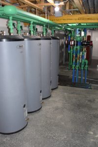
Figure 3: One of two central mechanical rooms for generating heated water for space heating and domestic hot water.
Using IEQ for the project ethos drove the compartmentalization of each unit. Each unit is served by independent hybrid HVAC systems using heated and chilled water from the central plants (Figures 3 and 4).
Since the community is sharing resources, including common walls between units, sound privacy is of utmost importance. There can be upwards of seven family members per unit, as such flanking paths needed to be mitigated by non-continuous flooring and wall assemblies.
There can also be outdoor noise issues when farm equipment is used near the housing units. Here the enclosure design (conservative window-to-wall ratio, reduced bridging and infiltration) was important to reduce outdoor sound effects. These floor, wall and ceiling details also helped the thermal performance in controlling the mean radiant temperature and thus the operative temperature in compliance with ASHRAE Standard 55 Thermal Environmental Conditions for Human Occupancy.
Lighting quality included window design for achieving acceptable daylight factors which also reduced sound transmission, radiant asymmetry and down drafts; and the design contributed to improved indoor air quality by minimizing the destruction of interior finishes due to exposure to shortwave (solar) radiation. The latter principle is a source control requirement implied in ASHRAE Standard 62.2 Ventilation and Acceptable Indoor Air Quality in Residential Buildings and CSA F326 Residential Mechanical Ventilation Systems. 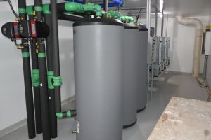
Air quality strategies also included reducing potential for moisture-related damage (through landscaping, enclosure designs and ventilation systems) and the use of low VOC finishes, radon mitigation systems and high-quality filtration products.
Odours and vibration are real problems in these types of communities due to agriculture production. Within the homes, internally-generated odours are prevented from migrating to another unit by the compartmentalization details and each unit’s independent exhaust and make up air systems. These details are important since pressure differentials across a common wall created by the operation of exhaust fan(s) could pull odours from one unit into another. However, the most challenging odour issue is related to the hog, poultry and cattle production and outdoor intakes for each home’s ventilation system.
In this dynamic the first source of control is within the production facility itself and then using specialty filtration within each housing unit. Though it’s almost impossible to keep an odour-free environment with natural ventilation, especially during the summer, the community understands some farming odours are part of their culture. Vibration from heavy farm machinery can sometimes be a problem mitigated by properly constructed roadways bypassing the housing complex.
Project Specifics
Building Systems:
- Below grade enclosure is 11-in. (280mm) ICF basement walls.
- 4-in. (100mm) slab bears on 2-in. (50mm) of rigid XPS insulation on a gravel radon plenum.
- Interior wood frame walls sheathed with OSB and then finished with drywall.
- Above grade walls are 6-in. (150mm) EPS panels with thermally isolated studs.
- Walls are vapour barriered, sealed and finished on the inside with drywall, and outside with weather barrier, strapping and PVC siding.
- The roof is assembled with engineered wood trusses, sheathed and finished with steel roofing. The attic is sealed with a polyethylene membrane, open cell spray foam and filled with cellulose.
- All PVC windows are triple sealed, triple pane and argon filled. Window glass with frame rated at U=0.14 Btu/ft² h F (0.79 W/m²K).
Mechanical Plants
The heating boilers serve the low temperature radiant floor systems and make up air heating coils. Both are designed to operate on reset with maximum supply of 120F (49C) and a 20F (11C) differential at design conditions of -35F (-37C). Boilers are also domestic water prioritized, staged to switch to 180F (82C) for charging the four 120 gal (454L) storage tanks through a preheat/boost/reheat brazed plate heat exchanger system for an 80F (44C) rise.
The cooling coils were specified by the client for a 45F (7C) entering fluid temperature and a 10F (6C) rise for conditioning the space and make up air. Cooling airflow per unit is 700 cfm (330L/s) at 1 ton/1200 ft2 (3.5 kW/112m2) based on 2200 ft2 (204m2) of cooled space.
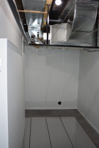
One of 28 mechanical rooms, one in each unit, with the radiant control closet to the left, air systems at the top and piping vault at the bottom. The central plants (Figures 3 and 4) eliminated 28 gas lines, venting and combustion air set ups; they also eliminated 28 heating and cooling plants and associated expansion tanks and fill assemblies.
Ventilation is comprised of a centrally-located variable speed in-line primary exhaust fan operating at 105 cfm (71 L/s) at 50% of total design exhaust flow. Ceiling located bathroom fans and range hoods provide additional exhaust capacity in conjunction with a unique odour exhaust system connected to each toilet.
The exhaust systems pull makeup air through an outdoor duct connected into the return air plenum. This air flow passes across the heating and cooling coils of the fan/coil unit for distribution through the supply air system when the fan/coil blower is off. The temperature regulation of the makeup air and air for cooling is done with a unique non-electric auto heat/cool change-over control—the control modulating fluid flow to each of the coils to maintain a client-controlled set point.
A room thermostat is used to turn on the blower on call for cooling (or optional stand by heating). Primary heating is radiant floors but in the shoulder seasons can be done with the fan/coil if the occupants wish to use it for the occasional cold spell.
Heated, chilled and domestic water from the central plants to each of the houses is carried through an in-ground PEX distribution network running under the building. Each home is fitted with a piping vault in the basement floor offering access to the pipes and expansion joints (see Figure 2).
Final Thoughts
Every project I have been involved with using an IDP has always resulted in better outcomes. The buildings provide higher indoor environmental quality using less energy, and the energy used is of the highest efficiency possible for the conditions.
The projects usually followed construction schedules and were completed on time. Often the capital cost premium was only slightly higher than normal because the client was willing to trade off expensive “short term” aesthetics for more practical solutions delivering better “lifetime” outcomes.
When one sees how integrated the service providers are to an IEQ metric one begins to understand how antiquated traditional segregated processes are and why they deliver such poor outcomes. Just like in business, everything is related and everything matters. <>
Notes:
Bean, R. (2014) Integrating Elements to Improve Comfort; Design wholeness can be achieved by proficiency in energy, environmental standards and guidelines. HPAC Magazine Canada. Accessed 2020.01.01 https://www.hpacmag.com/features/integrating-elements-to-improve-comfort/
Pearl, D. (2004) An Integrated Design Process (IDP) Canadian Architecture. Accessed 2020.01.01 https://www.canadianarchitect.com/an-integrated-design-process-idp/
Robert Bean is director of www.healthyheating.com, and founder of Indoor Climate Consultants Inc. He is a retired engineering technology professional (ASET and APEGA) who specialized in the design of indoor environments and high performance building systems.

