Keeping It Simple
May 16, 2023 | By John Siegenthaler
Hydronics systems don't have to be complex to be sophisticated.

(Adobe Stock)
If your office routine is anything like mine, you’re probably typing cryptic passwords into your desktop computer, laptop, smartphone or tablet throughout the day to access websites or cloud-based software that’s essential to your business.
Some of the sites you work with, especially those related to finances, likely require monthly updating on those passwords.
Do you keep essential documents on the cloud rather than a hard drive? Doing so should protect them from destruction if your office was compromised or destroyed by fire or flood, but under normal circumstances the pathway to those documents requires internet access and passage through gates latched with passwords.
If your router or internet service provider is down, or the wireless signal is weak because you’re out of your office on a job site, you can’t access any of those documents.
Is Connectivity Essential?
I admit that I could not do my job (at least for long) without access to the internet, and I suspect that’s true for most of you as well. Still, I remain unconvinced that all “good and modern” HVAC systems must be connected.
Today we are constantly being told that the Internet of Things (IoT) is becoming the hub for coordinated operation of the latest crop of HVAC devices such as thermostats, boilers, heat pumps, furnaces and even circulators.
Apparently all these devices need to “talk” with each other.
I often find myself “circling back” to the fundamental question: If all this microcircuitry, firmware, internet access, and layers of cybersecurity are essential—how did we ever create heating and cooling systems that kept millions of people comfortable for many decades, without all this digital overhead?
Perhaps our predecessors understood that there are some simple, reliable and accurate analog or mechanical approaches to controlling HVAC systems.
Contrast that with the modern product development mindset that increasingly defaults to the “cloud” for all control, updates and service-related information.
Simple, Reliable, and Even “Smart”
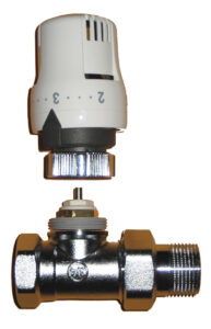
Figure 1a. The classic thermostatic radiator valve, the original “wireless” method of zoning a hydronic heating system.
One device that’s been around for many decades and continues to provide unique opportunities for creative designers is the thermostatic radiator valve (TRV for short, pictured Figure 1a, left).
If you’re unfamiliar with these devices, here’s a quick description based on the diagram in Figure 1b.
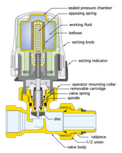
Figure 1b. Thermostatic radiator valve diagram.
The term thermostatic radiator valve represents a broad range of products. Most of them can be thought of as two subassemblies that work together: 1) a valve body, and 2) a thermostatic operator.
The valve body has a globe valve design with a spring-loaded shaft. The shaft moves up and down rather than rotating like the shaft in a typical globe valve.
When the shaft is fully pressed down the disc closes over the valve’s seat, preventing any flow. When the valve’s shaft is allowed to “spring” outward, the disc is a few millimeters above the seat, and the valve is at its maximum flow configuration.
The valve shown in Figure 1a would be mounted external to a radiator.
However, some panel radiators come with an integral valve typically mounted in the radiator’s upper right corner.
The thermostatic operator has a bellows that contains a “working fluid” or wax compound that expands when warmed, and contracts when cooled. This expansion and contraction cause the bellows to move.
In doing so it either presses inward on the valve’s spring-loaded shaft, or it allows that shaft to move outward. The shaft moves the disc toward or away from the valve’s orifice and thus determines the flow rate through the valve. More flow means more heat output from the radiator, and vice versa.
The thermostatic operator shown in Figure 1a simply screws onto the valve body. It has numbers from 1 to 5 on the knob. These are “comfort settings”: 1 is “cool” (about 55F/12.7C), 3 is typical heating season room temperature (about 68F/20C), and 5 is hot (about 79F/26C). Many TRV units also have a “snowflake” setting that’s meant to provide freeze protection by maintaining a space at about 45F/7C.
The occupant just turns the knob to align one of these numbers to the pointer, and the thermostatic operator takes it from there. If the room begins to cool slightly the valve automatically allows more flow through the radiator and vice versa. It’s analog cruise control for room comfort, and it doesn’t get much simpler. No wires, no batteries, no internet needed. TRVs were the original “wireless” method of zoning a hydronic heating system, and they remain so today.
Over the years we’ve specified hundreds of thermostatic valves in a wide range of hydronic systems. They’ve provided room-by-room comfort control in systems using fin-tube baseboard, towel warmers and a variety of panel radiators.
Simple But Elegant
As the global hydronics market continues to transition toward low temperature distribution systems, TRVs remain ready, willing and able to handle the comfort nuances present in modern low-energy buildings.
One of my favourite approaches to heating these buildings is a multi-zone distribution system using panel radiators with integral TRVs. All the radiators are connected into a home run distribution system as shown in Figure 2.
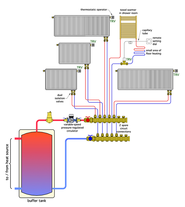
Figure 2. A simple multi-zone heating distribution system with all the radiators connected into a home run distribution system.
Heated water is supplied from a buffer tank, which could be heated by a boiler, heat pump, solar collectors or a combination of these heat sources.
Flow from the buffer tank to the manifold station is provided by a variable-speed pressure-regulated circulator, which automatically adjusts speed as the different TRVs open, close or modulate flow through their respective heat emitters.
Figure 2 shows more details that further expand the concept. One of them is the towel warmer tied in series with a small area of underfloor heating.
This is a great approach for a typical bathroom with tile flooring. Warm/dry towels and a barefoot-friendly floor. Try doing that with a mini-split.
Flow through the towel warmer and floor circuit is controlled by a TRV, but in this case the valve body is mounted a few feet away from the setting dial. A capillary tube connects the valve body and actuator to the setting dial. The working fluid passes back and forth through that tiny capillary tube.
A word of caution is in order: be sure to explain to the other trades on the job that the capillary tube is not a wire. You can’t cut it, splice it back together using a wire nut, and expect it to work! That’s a true story that occurred on a job I designed many years ago.
Another detail is to provide at least one extra set of connections on the manifold. This allows for simple future expansion of the system. Just mount the new radiator, screw the thermal operator onto the radiator’s integral valve, run a set of ½-in. PEX tubes to it, connect those tubes to the manifold, and you’ve got another independent heating zone. No wires, batteries or digital “handshakes” required.
Hydronic systems don’t have to be complex to be sophisticated.
They don’t have to be WiFi compatible to be elegant.
Simple devices like TRVs, combined with panel radiators and connected by a home run distribution system can deliver the ultimate goal of any heating system – superior comfort. And they pull it off without requiring a single password. <>