
Optimal Efficiency
September 22, 2020 | By Mike Miller
Exploring the proper application, operation and commissioning of residential ECM circulators in hydronic systems.
I absolutely believe that the electronically commutated motor (ECM) circulator is as significant to the hydronics industry as the modulating condensing (Mod/Con) boiler was when it arrived and still is. Just knowing that the circulator has the ability to adjust the flow of the system to better match the current load condition is awe-inspiring.
The circulator, which has always been an important part of the hydronic system, now “dovetails” with the heating equipment to raise the overall system efficiency, and not just the reduction in wattage consumption (full speed comparison of approximately 50% when compared to a traditional PSC motor), but also the lower return temperatures, longer equipment run times—longer steady-state efficiency, and with the turn-down ability of Mod/Cons, being able to reach and maintain the “thermal equilibrium” for longer time periods.
I have seen results of ECM circulator trials for well over a decade and they have always passed scrutiny. In 2015 a colleague replaced a delta-P controlled system circulator with a ‘newer’ delta-T unit. He used the same model circulator as his condensing boiler primary circulator and both of them were operating at a fixed delta-T of 30F.
He reached design temperature twice that season (~11F). His typical watt consumption on the boiler circ went from a fixed 80 watts (spd. med.) to something typical of 11 watts. And the bigger deal, his boiler return temperature was at its lowest average ever.
Applying ECM modes
We know ECM circulators deliver efficiencies, but it’s important to understand how to properly apply and set the correct mode of operation.
Most current residential ECM products have multiple operating modes: fixed speed (FS), constant pressure (CP), proportional pressure (PP) and some have an additional “Automatic” mode (which is also a PP mode) and some use “Delta T” (the ultimate Auto mode), and all of them, if applied correctly, can result in the highest overall efficiency.
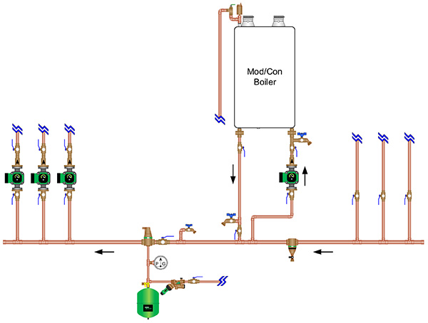
Figure 1
Fixed Speed (RPM) mode: (non-automatic) The fixed speed mode is appropriate when the application will not have changes in the operating points (varied hydraulic pressures down-stream of the circulator) like zone valves or actuators opening and closing. Examples of proper application of the fixed speed mode would include: single zone pumping, boiler circulator in a P/S piping configuration, domestic hot water (DHW) heat exchanger, pool or spa heat exchanger, snow/ice melting etc. (see Figure 1)
Constant Pressure mode: (automatic) The constant pressure mode is suited for the traditional North American piping scheme; these are typically multiple zone systems using individual zone valves or actuators on a preassembled manifold with a “system” circulator. The distinguishing difference of this layout is the paralleled supply and returns that run to and from the “near boiler piping” header in the mechanical area. This has also been called a “Home-Run” configuration. (see Figure 2)
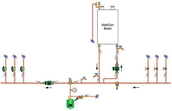
Figure 2
Proportional Pressure mode: (automatic) The proportional pressure mode is best suited for the “extended header” piping scheme. The distinctive difference of this layout is the supply and return piping is extended out in the building, and the branches/take-offs are out there as well. These multiple zone systems could be a mixture of different zone operating devices or terminal units such as: fan coils, fin-tube baseboard, cabinet unit heaters or simply several hydronic radiant floor manifolds. All these heat emitters could be controlled by different devices: on/off zone valves, actuators, modulating valves, mixing valves or diverting valves. (see Figure 3).
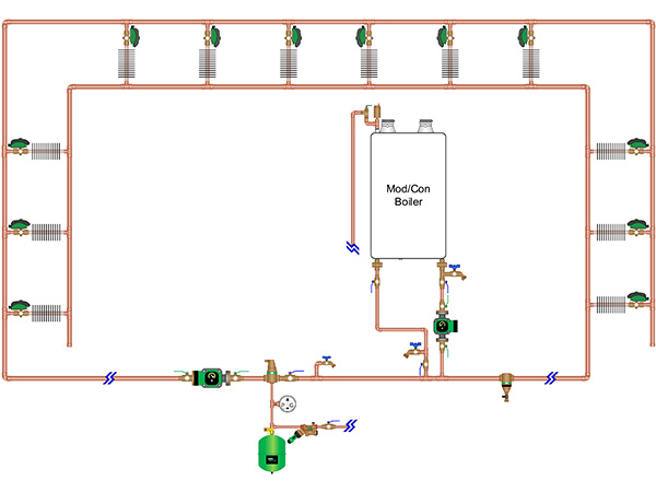
Figure 3
The ECM in brief
The primary benefit of ECM circulator technology is that it offers much more “controllability”. It allows complete control of the speed and direction of the circulators, and therefore complete, or more precise, control of the flow of hydronic systems.
The ECM also provides the capability to control the power consumption, and it allows the ability to know when something is wrong with the circ or motor. This information can be used to quickly assess a situation and make changes to the signal, its speed and its direction, or completely shut the motor off.
As previously discussed, I have looked at results from two particular different circulator input control methods; delta T (temperature differential) and delta P (pressure differential):
Delta P (∆P) controlled circs make their adjustments to the speed (rpm) based on what they feel. Things change in a multiple zone system “hydraulically” when zone valves close and open back up, or TRV’s squeeze close. So the motor feels these hydraulic changes within the system and can ramp down or back up depending on what is required at a given time. No special sensors or pressure transducers are required. Since hydraulic changes in the system can be felt almost instantly, the reaction time in a ∆P circ is very quick.
Delta T (∆T) controlled circs make their adjustments to the rpm based on what they measure. They look at feedback from two separate thermistors, one on the supply piping out to the system and the other on the return piping. When powered, these sensors constantly measure the temperatures and will ramp the circ’s motor down or up to maintain the “designed for” ∆T.
The ∆T is what you use in a flow rate (gallons per minute, GPM) calculation: GPM = Btuh / ∆T x 500; so to use a very important segment of this calculation to control the flow in a residential hydronic system can make sense for many applications. Since temperature changes in the system can take a little while to sense, the reaction time in a ∆T circ is a bit longer than a ∆P circ.
Proper mode selection/application
Fixed speed “non-automatic” mode is fairly straight forward as far as the piping scheme goes, so no additional explanation needed there. But a common question is, ‘Which “automatic” operating mode should the circulator be placed in; constant pressure (CP) or proportional pressure (PP)?’
The answer relies on how the system is, or will be, piped.
When a system is piped with parallel supply and returns brought back to the boiler as illustrated in the constant pressure mode example (Figure 2), one of the zones will set the maximum pressure drop (PD) required (plus a little for the near boiler piping and incidentals). The system circ still needs to be able to achieve the pressure drop requirement of that single zone, the one that set the PD target.
When the other zones close in the system, the GPM can drop dramatically (due to the circ’s ECM responding to the hydraulic change) but the head requirement is still based on the zone that set the PD target.
CP mode will always try to maintain a “fixed” desired head setting. For example, one model in the CP Mode has three fixed operating range settings: 5ft./hd, 10ft./hd and 15ft./hd. To select the right head setting requires some educated calculations/estimations. It’s always best to calculate the PD of the system so the correct setting can be used, but here’s a rule of thumb for generalized purposes: 5ft.= baseboard, 10ft.= typical radiant and 15ft.= fan coils or other high PD applications as long as the GPM requirement for any of them can be met.
Another point to understand, the circulator operating in CP mode will only slow down “automatically” if the system’s pressure drop from PVF (pipe valves and fittings) can induce enough resistance to maintain the particular head setting.
If you over estimate the PD of your system, let’s say you choose 15ft. head but the system will only impart 12ft., the circ will simply run out on its maximum rpm curve and it will not automatically slow down. (It’s better to slightly under-estimate/round down in the CP mode). So as zone valves close in the system, the circulator’s EC motor senses that resistance change then adjusts the rpm of the motor to a lower speed, hence the flow decreases but the motor speed will work to maintain the desired head setting.
PP mode is similar to the CP mode however it uses a “proportional” reset adjustment. As the PD in the system increases due to hydraulic changes (valves closing etc.) the EC motor senses those changes just as it did in the CP mode and will lower its speed but with a slight difference, it moves the head setting downward on a slight decline or pitch from what it was at max rpm.
The manufacturer sets up control logic in the circ’s microprocessor to a predetermined percentage of decline slope. For example, one model of ECM circulator in PP mode has three operating ranges: low, med or high. That means from a maximum head/GPM point on any of the three settings the performance range slopes back at 58% as it approaches ‘0’ GPM. The operating range slightly declines so that when the circulator senses hydraulic resistance it slows down and lets the head reduce along with the GPM.
Now with what I’ve covered in regards to CP and PP control options, let’s go back and think about a potential negative scenario. Picture a typical North American parallel S&R piped system, zoned with zone valves served with an ECM system circulator, similar to Figure 2, but that circ is set to run in a PP mode.
Under conditions approaching outdoor design temperature, this configuration may not give you the GPM and head required for a specific zone calling on its own. Recall that in PP mode the circ motor is working to lower its head based on a reduction in GPM requirement.
I’ve heard of people being called out for a “low or no heat call” when it was at or approaching design temperature. They’ve said the ∆T across certain zones was stretched way out and the quick fix was to change from PP to either CP or FS.
What about ∆T?
Delta T controlled system circulators are the easiest to discuss. The sensors, if located and installed correctly, will read the system’s temperature differential in “real-time” and adjust the motor speed accordingly. It will keep the ∆T at the “designed for” condition depending on the model, from 5F to 50F in one degree increments, typical settings of 20 to 30 (see Figure 4).
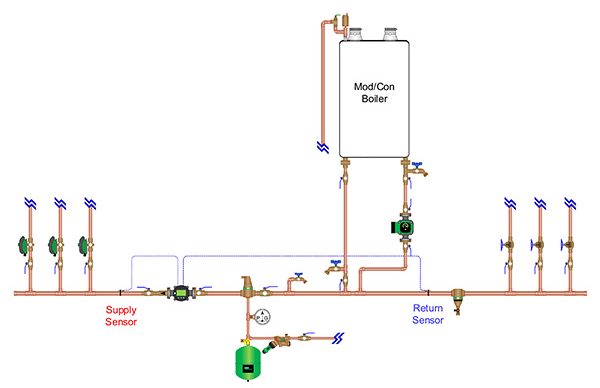
Figure 4
My hope is that the information in this article helps you better understand the application, operation and commissioning of residential ECM circulators. As you apply this knowledge we all win because our collective “systems” get better and more efficient.
A special thank you to Rick Mayo, Taco Comfort Solutions products and applications instructor, Western Region, for his enormous contribution to making this article happen. <>
 Mike Miller is director of sales, commercial building services, Canada with Taco Inc.
