
Pel-Air Systems: Pellet Boilers Meet Forced Air Heating
April 5, 2022 | By John Siegenthaler
Exploring design options for retrofitting a pellet boiler to a forced-air heating system.
I’ve described pellet-fueled boiler applications in several past issues of HPAC, and all of them have been situations where the boiler supplied a hydronic distribution system.
While such applications are certainly the prevailing way pellet boilers are used, they are not the only option. It’s possible to couple a pellet boiler to a forced air distribution system.
Most of these applications will be retrofits—perhaps a way to transition a central forced air system away from fossil fuel and onto renewable wood pellets. The economics of such a conversion are increasingly attractive as fossil fuel prices soar.
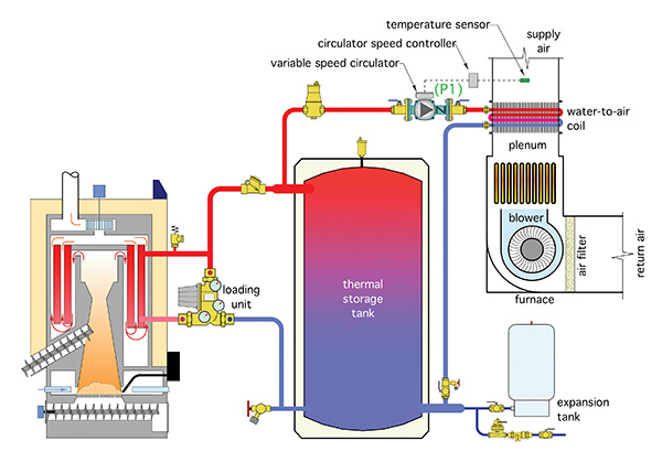
Figure 1: Basic pellet boiler system layout.
Figure 1 (above) shows a basic system layout. The details between the boiler and thermal storage tank are typical. In this case a “loading unit,” which combines a thermostatic mixing valve and circulator provides flow between the boiler and thermal storage tank. It also prevents sustained flue gas condensation within the boiler by elevating the boiler inlet water temperature above 130F (54.4C) whenever possible.
The thermal storage tank is piped in a “three-pipe” configuration. This allows hot water from the boiler to flow directly to the load if the pellet boiler is operating at the same time as the load.
It also ensures that the thermal mass of the storage tank is fully “engaged” in the energy transfer process. This is critically important for any hydronic system with a biomass heat source.
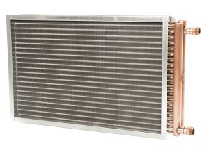 The heat emitter is a coil mounted in the discharge plenum of a furnace. An example of such a radiant coil is shown in here (left).
Most installations will require sheet metal transitions to be fabricated to join the coil to the furnace plenum as well as to the downstream ducting.
Never mount the coil on the air inlet to a furnace. Doing so could heat the blower motor above its maximum rated operating temperature causing it to lockout or burnout. It’s also likely that such a situation would void the furnace’s warranty due to the potential for high entering air temperatures.
For the system in Figure 1, water flow through the coil is regulated by a variable speed circulator. A closed control loop is established by monitoring the air temperature downstream of the coil.
If this temperature begins to drop below a preset value, such as 110F (43C), the circulator increases speed, which increases heat output from the coil, and vice versa.
There are circulators on the market that have self-contained logic for setpoint temperature control. The temperature sensor in the discharge duct can be wired directly to such a circulator.
Circulators without this functionality, but equipped with either an analog input, (4-20 ma, or 0-10 VDC), or a digital input, (BACnet, LONworks, or PWM), can be regulated by one of several currently available temperature controllers.
Controlling the discharge air temperature is important in this type of application. That’s because the temperature of the water supplied to the coil from the thermal storage tank could be as high as 190F (88C), and perhaps as low as five degrees above the desired leaving air temperature. Without flow regulation there would be times when scorching hot air is pushed through the supply ducting and into the conditioned space.
The low density of this air would immediately cause it to rise toward the ceiling, and thus set up excessive air temperature stratification. Overheated air would also cause rapid thermostat cycles, and guaranteed comfort complaints.
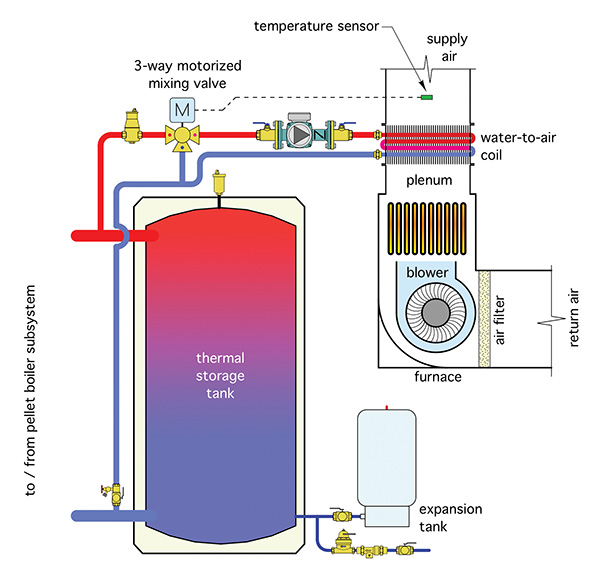
Figure 2: Piping design incorporating a three-way mixing valve.
Another way to control the discharge air temperature is using a three-way mixing valve. The piping for this is shown in Figure 2 (above).
Air-side Design
Another important consideration is the drop in static pressure as air flows through the plenum coil. Most furnaces have ratings for air flow rate versus the external static pressure of the distribution system to which they connect.
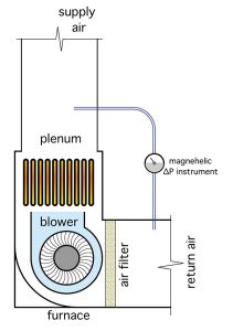
Figure 3: Connect a magnehelic gauge to measure the pressure drop after the coil is installed.
In most systems the static pressure is created solely by the duct system. However, when a coil is added to the plenum it will definitely increase the total static pressure the furnace’s blower operates against.
In applications where there’s an existing furnace it’s possible to measure the current static pressure drop by connecting a magnehelic gauge connected as shown in Figure 3 (right).
Coil manufacturers can supply data that lists the static pressure drop across their coils as a function of the air flow rate through the coil. Use this data to determine the added static pressure at the nominal air flow rate the system needs to provide.
If the existing forced-air distribution system already has a cooling coil installed, it’s very unlikely there will be sufficient static pressure capacity to accommodate a hot water coil. In this case it’s better to install a separate air handler in parallel with the furnace as shown in Figure 4 (below).
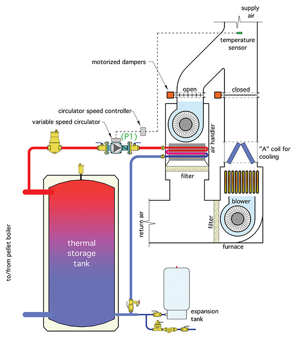
Figure 4: Install a separate air handler in parallel if both heating and cooling are required.
Motorized dampers should be installed as shown. They open only when their associated air handler is operating. When closed they prevent air flow from “short circuiting” through the inactive air handler (or furnace).
Future Expansions
A unique benefit of this approach is that it allows heat from the pellet boiler to be used for ancillary loads—domestic water heating is one example. Adding a manifold station and using it to supply some panel radiators, towel warmers, or radiant panel circuits is another.
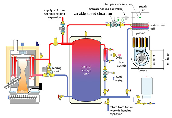
Figure 5: This diagram shows domestic water heating using brazed plate heat exchanger as well as supply and return piping for another independently controlled hydronics heating zone.
The system in Figure 5 (above) shows an “on demand” subassembly for heating domestic water using a stainless-steel brazed plate heat exchanger, small circulator, and a domestic water flow switch.
It also shows supply and return piping for another independently controlled heating zone. There are many possible variations. The key concept is the ability to expand the system for the future needs of the building without extensive modifications.
I’ll close by admitting that I prefer hydronic heating distribution systems whenever possible. But I’m also a realist. There are a lot of forced air systems out there that could potentially undergo a pellet boiler “make-over”. Doing so not only transitions the system to a renewable fuel, it also opens up a wide range of possibilities to suit the future needs of the building and its occupants. <>

John Siegenthaler

