
We need thermal storage tanks with lower standby loss
December 19, 2016 | By John Siegenthaler
Thermal storage tanks play an important role in several types of hydronic heating and cooling systems. This is especially true of systems with renewable energy heat sources such as solar thermal collectors, heat pumps, or biomass boilers.
The most common uses of thermal storage in hydronic systems include:
• Buffering an on/off heat source against short cycling
• Buffering a modulating heat source against short cycling
• Reducing the size of a heat source relative to peak load
• Providing thermal mass to buffer domestic water heating loads
• Storing heat supplied using favourable time-of-use electrical rates
• Storing surplus heat produced by a solar thermal system
• Storing surplus heat produced by a biomass boiler system
During the design process for a hydronic system that will include thermal storage, the volume of that tank often becomes the centre of attention. For example, should the thermal storage tank associated with 80,000 Btu/hr rated pellet-fired boiler be 80 gallons or 160 gallons? Or, how many gallons of thermal storage are needed for each square foot of solar thermal collector in the system? There are strong and widely varying opinions on the optimal volume of a thermal storage tank in different system applications.
However, opinions of what type of insulation system is used on a thermal storage tank are usually not as strong and varying. In many cases designers simply accept the insulation system that a given tank manufacturer provides, assuming that it is adequate for whatever function the tank will provide.
Most pre-insulated thermal storage tanks sold on the North American market have no more than a nominal two inches of polyurethane foam insulation. This provides a nominal R-value of 12F•hr•ft²/Btu. That is about half the R-value that some modern building codes require in exterior walls, and about 20 per cent of the R-value often recommended for attics in cold climates. In my opinion it is not enough.
STATUS QUO
I have always been amazed at the ability of a vacuum-insulated Thermos® bottle to keep liquids hot. Fill the bottle with steaming hot coffee in the morning, and it is still steaming hot several hours later. I like to idealize thermal storage tanks as large Thermos® bottles. Put heat in when it is available, and just about all of it remains “parked” for several hours, maybe even a day or two, until it is needed.
From what I have observed over the years, most pre-insulated thermal storage tanks sold in North America have a ways to go to perform like large Thermos® bottles. Since the cost and complexity of vacuum-based methods for reducing heat loss are not ready to be applied to large thermal storage tanks, better conventional insulation would appear to be the readily available solution.
I have asked some manufacturers to consider offering thermal storage tanks with insulation that goes significantly beyond the nominal two inches of foam. Some of their responses could be paraphrased as follows:
1. A better insulated tank would cost more, which puts it at a competitive disadvantage.
2. None of my customers are asking for a better insulated tank.
3. The tank jacket would have to be larger and this would complicate shipping
These responses are understandable from a sales and marketing perspective. But they leave us with essentially the same tanks year after year, with no path for improvement.
Published information about the standby heat loss of pre-insulated thermal storage tanks sold in North American over the last few years have included claims of tanks that only loose 1F per hour (with no stated reference conditions at which this heat loss occurs). For comparison, some European manufacturers offer thermal storage tanks that claim losses of only 0.1C (0.18F) per hour (again with no stated reference conditions).
RUNNING THE NUMBERS
Analyzing the difference in tank heat loss caused by different insulation systems can be complex. In theory, the analysis should account for the vertical temperature stratification within the tank, that is the temperature of the water at the top of the tank is higher than the temperature at the bottom of the tank. It should also account for the thermal conductivity of the material used to make the tank shell.
A steel tank shell, for example, would conduct heat faster than a tank made of polymer or other nonmetallic material. It should account for the convection conditions of air surrounding the tank, the thermal emissivity of the tank’s outer surfaces, and the exact shape of the tank. It should even account for the heat losses associated with metal piping or structural legs connected to the tank and penetrating through the insulation.
Creating an engineering model for tank heat loss that accurately accounts for all these nuances is a good subject for a PhD thesis rather than an HPAC article.
Still, I want to provide you with a mathematical tool that can be used to get a “reasonable” estimate of how different insulation systems could affect heat loss from a thermal storage tank. The following formulas are that tool. They are based on a vertically oriented cylindrical tank, and include several assumptions that greatly simplify the math.
Here are the assumptions:
1. The tank has the same type and thickness of insulation on all surfaces.
2. The tank has a flat top and a flat bottom.
3. The tank is surrounded by air at the same temperature (top, sides, and bottom).
4. The R-value of the air film on the outer surface of the tank insulation is negligible in comparison to the R-value of the tank insulation.
5. The air temperature surrounding the tank remains constant hour after hour.
6. There is no conduction heat loss from any piping or support legs that penetrate the insulation on the tank.
7. The thermal resistance of the tank wall material is negligible in comparison to the R-value of the tank insulation.
8. The tank has a linear temperature gradient from bottom to top
FOR AN INSTANT
The instantaneous rate of heat loss from a tank, based on the stated assumptions, can be estimated using Formula 1:
Where:
Q = instantaneous rate of heat loss from tank (Btu/hr)
do = outer diameter of tank insulation (ft)
di = inner diameter of tank insulation (ft)
L = height of cylindrical tank (ft)
k = thermal conductivity of tank sidewall insulation (Btu/ºF•hr•ft)
Rtb = R-value of insulation on top and bottom of tank (ºF•hr•ft²/Btu)
pi = 3.141592654
Tw = average temperature of water in tank (ºF)
Ta = temperature of air surrounding tank in tank (ºF)
The relevant dimensions can be seen in Figure 1.
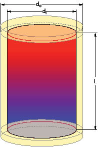
Figure 1
Here is an example. Assume that a flat-ended thermal storage tank measure 35-inches in diameter, and 80-inches tall. Assume that all surfaces of the tank have three-inch thick polyurethane insulation (R= 6.0F•hr•ft2/Btu per inch, and k = 0.01389 Btu/hr•ft•ºF). The top-to-bottom average water temperature in the tank is 150F. The air temperature surrounding the tank is 70F. Estimate the instantaneous rate of heat loss from the tank under these conditions.
Formula 1
Before using Formula 1 it is important to express all quantities in the units noted under Formula 1. The following unit conversions are necessary:
di = 35 inch = 2.9167 ft
do = (35+3+3) inch = 41 inch = 3.4167 ft
Rtb = 3 x (6.0/inch) = 18.0 (ºF•hr•ft²/Btu)
Putting the numbers into Formula 1, and carefully processing them through a calculator yields: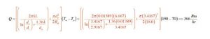
Keep in mind that the tank is constantly losing heat, and therefore its temperature is constantly decreasing. That means that the rate of heat loss calculated using Formula 1 is only valid for an instant (e.g., when the internal average water temperature in the tank is exactly 150F). An instant later, the temperature of the water in the tank is slightly lower. It might only be 0.0001F lower, but it is still lower. This also means that the rate of heat loss will be lower. Thus, another formula is needed to evaluate how the water temperature in the tank decreases due to standby heat loss over time.
AS TIME PASSES
The average water temperature in the tank, due solely to standby heat loss, can be estimated using Formula 2*.
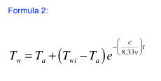
Formula 2
Where:
Ta = room air temperature (ºF)
Twi = initial average temperature of tank water (ºF)
t = time (hours)
v = volume of water in tank (gallons)
e = 2.718281828
* This formula is also based on the same assumptions as Formula 1.
Also be sure that the expression following the “e” in Formula 2 is treated as an exponent, not a multiplier.
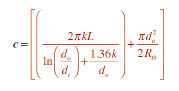
Notice that the expression for “c” is the same as the portion of Formula 1 that appears in red and before the expression (Tw-Ta). The value of “c” is entirely defined by the dimensions and insulation of the storage tank. If you calculated it for use in Formula 1, you can use the same value in Formula 2.
Here is another example. Assume that the storage tank from the previous example starts at an initial average water temperature of 150F; that no heat is added to the tank; and the only heat removed is through standby heat loss. The tank is surrounded by 70F air. Estimate the tank’s average temperature 24 hours later.
Solution: The value of “c” from the previous example 4.57.
Formula 2 also requires the tank’s volume in gallons. This can be determined using Formula 3.
Where:
v = tank volume (gallons)
di = inside diameter of tank shell (inches)
h = height of tank shell (inches)
When this volume and the other stated conditions are entered into Formula 2, and the numbers are carefully processed through a calculator, the result is as follows:
![]() This calculation estimates that the average water temperature in the tank drops by just over 3F during the 24-hour period. That is an average of 0.125F per hour. This is a relatively low rate of heat loss. However, remember that this calculation does not account for heat loss from piping – especially uninsulated piping – that may be connected to the tank. Inevitably, there will be piping connected to the tank and this will increase the rate of heat loss. Obviously those losses will be reduced if the piping connected to the tank is insulated.
This calculation estimates that the average water temperature in the tank drops by just over 3F during the 24-hour period. That is an average of 0.125F per hour. This is a relatively low rate of heat loss. However, remember that this calculation does not account for heat loss from piping – especially uninsulated piping – that may be connected to the tank. Inevitably, there will be piping connected to the tank and this will increase the rate of heat loss. Obviously those losses will be reduced if the piping connected to the tank is insulated.
A COMPARISON
I used Formulas 1, 2, and 3 to compare the standby heat loss of four combinations of insulation material and thickness. These combinations and their associated properties are as follows:
• 2″ polyurethane foam (R= 6F•hr•ft²/Btu per inch thickness), (k=0.01389 Btu/hr•ft•ºF)
• 4″ polyurethane foam (R= 6F•hr•ft²/Btu per inch thickness), (k=0.01389 Btu/hr•ft•ºF)
• 2″ fibreglass (R= 3.5F•hr•ft²/Btu per inch thickness), (k=0.0238 Btu/hr•ft•ºF)
• 4″ fibreglass (R= 3.5F•hr•ft²/Btu per inch thickness), (k=0.0238 Btu/hr•ft•ºF)
These insulation materials were all assumed to be applied to the tank used in the previous example calculations (that is 35 inch diameter x 80 inch tall, with 333 gallon volume). The initial average water temperature in the tank was 150F and the air temperature surrounding the tank remained at 70F.
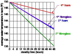
Figure 2 Tank water temperature
Figure 2 shows the resulting drop in tank water temperature for each insulation scenario.
It is not surprising that the four-inch foam insulation system yields the lowest rate of temperature drop, while the two-inch fibreglass insulation produced the fastest temperature drop. The former lost only 2.5F in its average water temperature over 48 hours. That is a pretty good Thermos® bottle. The latter experienced a drop in average water temperature of almost 14F over the same 48 hours. Interestingly, the two-inch foam and four-inch fibreglass insulation options produced nearly identical standby temperature drop over time. Remember that these temperature declines do not include any heat loss effects for connected piping or support legs that penetrate the insulation.
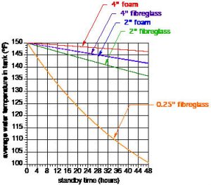
Figure 3 Insulation comparison
As such they are likely to underestimate the temperature drops associated with real tanks with such attachments.
If you want to make more comparisons, I suggest that you set up a spreadsheet that uses Formulas 1, 2 and 3. Keep in mind that Formula 1 and 2 cannot have an R-value of 0. If you want to consider the case of a very poorly-insulated tank I suggest you use a thickness of 0.25 inch and the corresponding R value and k value for the insulation material. I did this for fibreglass insulation, and the results are shown in Figure 3 along with the previous temperature decline curves.
ROOM FOR IMPROVEMENT
In the interest of reducing standby heat loss, I urge North American manufacturers of pre-insulated thermal storage tanks to offer products with better insulation, along with other carefully considered details.
John Siegenthaler, P.E., is a mechanical engineering graduate of Rensselaer Polytechnic Institute and a licensed professional engineer. He has over 34 years experience in designing modern hydronic heating systems. Siegenthaler’s latest book, Heating with Renewable Energy, was released recently (see www.hydronicpros.com for more information).
