
Getting it right – part II: Troubleshooting hydronic controls
March 1, 2018 | By Mike Miller
 As it was noted in Part I of this series (see HPAC February 2018), control systems are often blamed when something is not operating as expected. More often than not, if hydronic controls do not perform as needed, something happened on the installation or programming side of things.
There is absolutely nothing that will minimize downtime and troubleshooting more than getting the system installed right the first time. Nothing will ever replace the need for solid training and acquiring an understanding of the product itself, along with the installation side of things, in advance of working with the product.
In Part I the focus was on challenges surrounding sensors. In this issue the focus is on sizing and piping the controlled device.
 On/Off devices can be looked at somewhat similarly, but the following is specific to mixing requirements, one of the more common challenges with hydronic controls.
When controlling devices do not seem to be able to meet setpoint, there is usually one of the following three things to blame. The first could be the hydronic controls algorithm; unless the algorithm was written on the controller in the field and very recently, in most cases this can be eliminated as a cause of the problem.
Related: Getting it right – part I
Most controllers come with canned software that has been developed, tried and tested over a period of time. It is fairly unlikely that a proven control algorithm will behave differently in your application.
The more common challenges with hydronic controls are caused by improper sizing or piping of the equipment used.
Device Sizing
Whether the device is controlling air or fluid, it needs to be sized to the appropriate needs. For air systems, devices need to be sized based on cubic feet per minute (CFM) of air velocity needed. Using fluids, we size based on gallons per minute (gpm) of flow.
Let’s focus on controlled devices based on fluids to attain fluid temperature control. Sizing the device just right allows for the control algorithm to take advantage of the full throttling range of the mixing device. If a device is oversized, the most commonly noticed performance is the device seems to be hunting back and forth, that is a mixing valve opening and closing rapidly rather than small movements to maintain a particular setpoint.
The same is true when using an injection pump. When oversized, the pump will ramp up and ramp down randomly without being able to stabilize to maintain a setpoint. A cautionary note: never size the mixing device to the pipe size needed to distribute the fluid. The following example explains why.
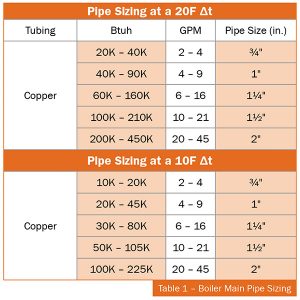
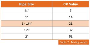
A 100,000 Btuh radiant system operating off a 10F deltaT requires 20 gpm flow (Flow = Btuh/(deltaT x 500)). The system piping, if in copper, would be 1-1/2 in. according to Table 1, where the mixing valve would only need to be at 1-1/4 in., according to Table 2 (see CV = volume of flow in GPM at one psi pressure drop).
Another commonly used mixing system is the variable speed pump injection system. In this system the speed of a pump is controlled by changing the frequency and the voltage supplied to the pump, effectively modulating the amount of heat transfer between two loops to attain water temperature control.
Pumps on the market vary output based on head pressure in the system. A balancing valve is used on the injection loop’s return to fine-tune the output and to achieve a 100 per cent throttling range. For sizing, use the same simple flow calculation all wet heads should be familiar with: Injection flow = Btuh/(deltaT x 500).
Except that in this example the deltaT is the temperature difference of primary loop supply and secondary/radiant loop return, assuming that in this radiant example the required supply fluid temperature would be 120F.
Formula 1
Injection Flow = 100,000 Btuh/((180F-110F) x 500) = 2.85 GPM
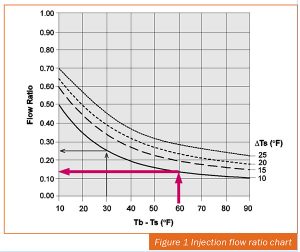 The exact method of sizing an injection pump would require a little more than Formula 1. It would require you to have the following, along with the injection flow ratio chart in Figure 1:
Primary/boiler loop supply tempera-
ture (Tb)
Secondary/radiant supply temperature (Ts)
Secondary/radiant system deltaT (deltaTs)
Seconday/radiant system flow rate (SF)
Using the chart in Figure 1, identify the Flow Ratio (FR) in GPM using 180F (Tb) – 120F (Ts) and 10F (deltaTs).
For this example, that would be roughly 0.14 GPM. Now, take your 20 GPM System Flow SF x 0.14 GPM Flow Ratio (FR) = 2.8 GPM design injection flow rate.
Select the best wet rotor circulator, which can give you that flow and use the balancing valve on the Injection loop return to adjust the heat pressure to suit.
 Device Piping
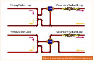
Figure 2 shows the proper installation of a mixing device off the primary loop. Two closely spaced tees allow for hydraulic isolation of the primary loop and the secondary/radiant loop, effectively preventing the two pumps from working in series. The hydraulic separation requires very few basic requirements to be followed in order to attain effective isolation.
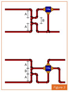 Those are shown in Figure 3.
Where:
A = MIN 6x diameter of primary loop pipe size
B = MAX 4x diameter of primary loop pipe size (there is no such things as putting them too close together).
Hydraulic separation can also be achieved by engineered devices such as low loss headers and four pipe air and dirt separators.
The piping requirements of the injection pumps is very similar to the piping requirements of mixing valves.
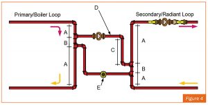 A and B remain the same for variable speed injection systems as shown in Figure 4. Some additional requirements include:
C = MIN of 12 in. drop (creates a thermal trap and prevent convective heat transfer)
D = MIN one pipe diameter smaller than that of secondary/radiant loop
E = Balancing or globe valve for flow balancing.
The controller can only do its job and perform as expected when the sizing and piping of the mixing devices are correct.
Hydraulic separation is also very critical when you have multiple pumps on the same distribution piping system. In some large mechanical systems, larger primary pumps are installed to circulate the fluid through the building.
More often than not, two way on/off or modulating hydronic controls valves are used to provide flow through the heat emitters/terminal units throughout the building. But should one choose to use pumps on the terminal units as well, it is absolutely important to decouple the load from the distribution piping system through either primary/secondary and closely spaced tees as per above, or by using other means of hydraulic separation as mentioned earlier.
Failing to address the issue will create ongoing problems. These will be mistakenly attributed to hydronic controls. Failing to decouple one pump from another will result in flow in a loop or zones where you may not want it at a given time.
Other piping and sizing challenges may appear in a controlled system, but an understanding of the issues covered here will serve you well when troubleshooting systems.
Look for Part III of this series in HPAC May 2018.
 Mike Miller is director of sales, commercial building services, Canada with Taco Inc. and a past chair of the Canadian Hydronics Council (CHC). He can be reached at hydronicsmike@taco-hvac.com.

