
Strategic Modifications
January 30, 2023 | By John Siegenthaler
Existing series distribution systems can be modified to accommodate lower water temperatures generated from modern heat pumps.

(image: Adobe Stock)
Heat pumps continue to gain market share as hydronic heat sources, and this category includes both geothermal water-to-water heat pumps as well as air-to-water heat pumps.
All heat pumps perform better when the “temperature lift” from the low temperature source to the higher temperature load is reduced. In the case of air-to-water heat pumps there’s very little any designer can do to influence the temperature of outside air (other than placing the unit on the sunny side of the building to get a slight “micro climate” benefit on sunny days).
Those designing geothermal systems can opt for larger earth loops (e.g., more pipe in the ground), but there’s a rapidly diminishing return on the added cost of doing so.
The load side of the system is where designers can provide greater influence on overall system performance.
Keeping the required supply water temperatures as low as possible will optimize the coefficient of performance (COP) of any hydronic heat pump. My recommendation is that any distribution system supplied from a hydronic heat pump should be able to deliver design load heat output without exceeding a supply water temperature of 120F (49C).
Starting point
There are sure to be increasing circumstances where system designers are asked to add a heat pump to a “legacy” hydronic system. The most common configuration is likely to be a boiler supplying fin-tube baseboard heat emitters. Figure 1 shows two common piping configurations for such systems (a series loop or split series circuit).
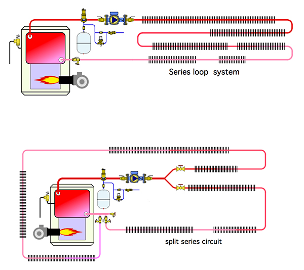
Figure 1. Two typical designs with fin tube radiators.
Most of these systems were originally designed around relatively high supply water temperatures, in the range of 180F to 200F at design load conditions. Such temperatures are well beyond the working range of currently available hydronic heat pumps.
It is possible to salvage these legacy high temperature systems for use with hydronic heat pumps, and here are two approaches that can be used individually or together.
- Lower the building’s design heating load though improvement to its thermal envelope (e.g., added insulation, new windows, air sealing, etc.).
- Add heat emitters to the hydronic distribution system.
When building envelope improvements are used the reduced supply water temperature at design load can be estimated using Formula 1.
Formula 1:
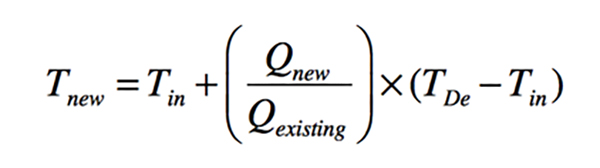
Tnew = supply water temperature at design load after building envelope improvements (F)
Tin = desired indoor air temperature (F)
Qnew = design heating load after building envelope improvements (Btu/h)
Qexisting = existing design heating load (before improvements) (Btu/h)
TDe = existing supply water temperature at design load (before improvements) (F)
For example, assume an existing building has a design heating load of 100,000 Btu/h, based on maintaining an interior temperature of 70F. The existing hydronic distribution system uses standard fin-tube baseboard and requires a supply water temperature of 180F at design load conditions. Also assume that improvements to the building envelope will reduce this design load from 100,000 Btu/h to 70,000 Btu/h. The new supply water temperature for the existing distribution system under design load conditions can be estimated as:
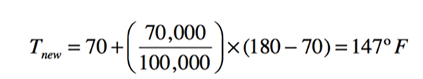
Any further reduction in building load would have a corresponding drop in design load supply water temperature. This approach makes sense when the option of adding heat emitters is impractical.
Piping mods
The other option for lowering the required water temperature to allow for good heat pump performance is to add heat emitters. The fundamental concept is simple: the greater the total surface area of the system’s heat emitters, the lower the required water temperature for given rate of heat output.
Adding baseboard, panel radiator, radiant panel circuits or fan-coils to an existing series loop system presents several challenges:
- Can the existing piping loop be configured for the new emitters?
- Will the temperature drops created by adding more heat emitters in a series cause significant drops in output to downstream emitters?
- Will the head loss of an extended series loop be too high for the existing circulator, or perhaps even a new higher head circulator?
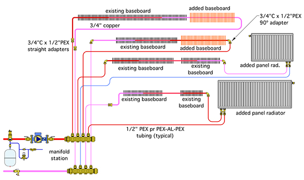
Figure 2. A modified distribution system, adding heat emitters to an existing series loop system with fun tube radiators.
Rather than simply extending an existing series loop system I recommend converting it to a hybrid parallel/series system. Figure 2 (above) shows an example in which the original series loop system has been “segmented” into parallel piping branches, and new heat emitters have been added.
In this example, the revised system has four parallel branches. Each branch has two or three heat emitters, some original and some new. As much of the original copper tubing as possible has been retained, and ½-in. PEX tubing has been used to connect the copper tube segments back to a manifold station. The latter is easier and faster than trying to splice the new piping segment back together with copper tubing. All the PEX is routed back to a manifold station.
Making the cuts
There are several factors that will influence how the new heat emitters are piped into the system. They include the following:
- Where can installers access the existing piping?
- Are there building areas that need more heat output?
- Does it make sense to potentially divide the distribution system into separate zones?
- Are there multiple heat emitters within a given space that can remain intact as one of the parallel branches?
- What are the flow resistance characteristics of the new heat emitter relative to those of the existing heat emitters?
- What type of control will be used to regulate heat output to each zone of the distribution system?
There is no universal approach. Every situation must be evaluated individually while weighing these factors to determine the best fit for that project.
The hybrid parallel/series system will likely reduce the head loss of a system relative to the series loop, which will result in a higher total system flow rate (assuming the same circulator is used). It also allows heat emitters near the end of the loop to operate at a slightly higher average water temperature and therefore slightly higher heat output.
Final polish
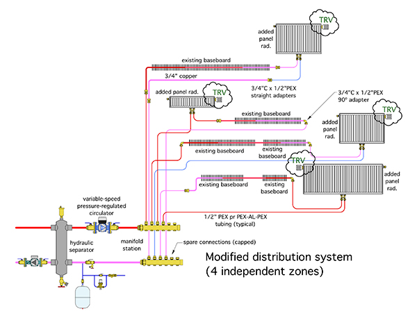
Figure 3. One concept for modifying a series loop into a multi-zone system.
One of the benefits of converting the series loop to a hybrid parallel/series system is that each parallel branch could be operated as a separate zone. Flow through each zone could be regulated by including thermostatic radiator valves in each branch circuit, or by adding valve actuators to the manifold station. Figure 3 (above) shows an example where thermostatic radiator valves (TRVs) are used.
The modified system now includes a variable speed pressure regulated circulator set to maintain a constant differential pressure. The circulator automatically changes speed as the TRVs open, close, or modulate flow. A hydraulic separator has been added to isolate the pressure dynamics of the variable speed circulator from the remainder of the system.
There are virtually limitless possibilities of how these concepts can be used, but what’s clear is these concepts, along with modern hydronic hardware, allow legacy hydronic systems to be upgraded for lower temperature operation and compatibility with the growing market for hydronic heat pumps.

John Siegenthaler

