
READER FAVOURITE FROM HPAC’S ARCHIVE: The Wide World Of Hydraulic Separation
June 2, 2014 | By JOHN SIEGENTHALER
Several methods to achieve the same results.
In essence, that is what hydraulic separation is: The ability of two or more circulators within the same piping system to simultaneously operate without interfering with each other.
Properly designed and installed primary/secondary piping can achieve hydraulic separation between all circulators. However, primary/secondary piping is not the only way to achieve hydraulic separation, as depicted in Figure 1.
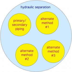
Figure 1 Methods To Achieve Hydraulic Separation
Think of hydraulic separation as the “broad topic,” whereas primary/secondary piping is one of several subtopics. This article will show you several other ways to achieve the same desirable results delivered by classic primary/secondary piping, in ways that often simplify the system and reduce its installation cost.
GOOD AND BAD HEADERS
Before detailing other methods of hydraulic separation, it is important to understand the role of headers in a hydronic system. The “ideal” header in any hydronic system would simply split up the flow entering it into the branch circuits attached to it with zero head loss. The spherical header shown in Figure 2 would be a very close approximation of this ideal concept.
Imagine piping coming out of this spherical header in all directions, like a copper basketball with tubes coming out all over its surface. The water would be very “content” to flow through such a header, but imagine how this would look in a typical mechanical room. In short, it would look terrible. It would take up lots of room and be very difficult to install using standard methods. Bottom line: We do not build headers like this. Not because they would not work, but because of these other practical and aesthetic reasons.
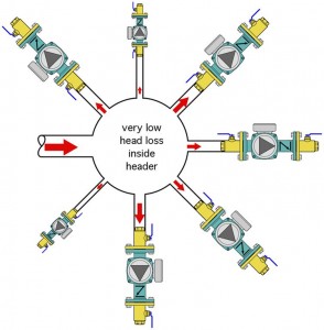
Figure 2 Spherical Header
Instead, we approximate the favourable fluid mechanics offered by the copper basketball header with standard hardware that looks good and lays out neatly in a mechanical room, as depicted in Figure 3.
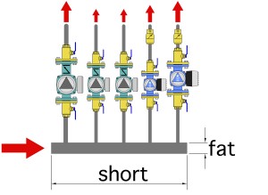
Figure 3 The Mechanical Room Reality
I like to call these “short/fat” headers. Simply put, the shorter the header and the greater its diameter, the closer it comes to approximating the copper basketball header. Remember, the goal is to split up the flow into the branches with as little head loss as possible.
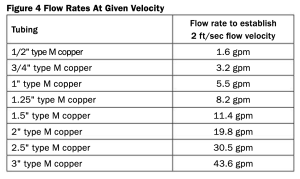
So, here is something that every hydronic system designer can easily remember: Short/fat headers are good and long/skinny headers are bad. It is always good to keep the headers in your systems as short as practical and to use a tube size that keeps the flow velocity when all branch circuits supplied by the header are operating at no higher than two feet per second. Figure 4 is a table that lists the flow rates corresponding to flow velocities of two feet per second for type M copper tube.
BEYOND THE HEADERS
Short/fat headers provide hydraulic separation between the circulators connected to them. These circulators can be different sizes. Some may be variable speed circulators while others operate at fixed speeds. Hydraulic separation occurs because the head loss (and thus the pressure drop) along the length of the headers is very low.
To maintain the hydraulic separation afforded by short/fat headers it is important that the headers connect to a piping assembly that itself creates very low head loss. One arrangement that achieves this is simply connecting the headers to a low flow resistance heat source, such as a cast iron boiler, or a “tank type” hydronic heat source, as shown in Figure 5.
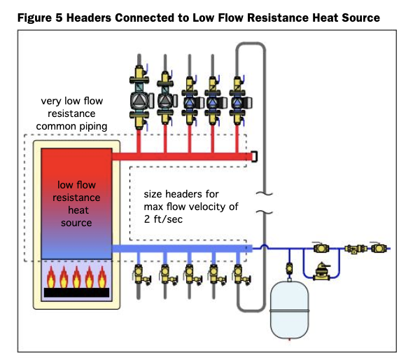 Both of these heat sources create very little head loss. When combined with short/fat headers, the “common piping” assembly, outlined with the dashed lines, creates very little head loss, even when all the circulators are operating. The lack of any significant head loss in the common piping is what prevents circulators from “feeling” each other’s presence in the system. If the circulators cannot “feel” each other, they cannot interfere with each other.
The piping in Figure 5 also provides the same supply water temperature to each load served by the header. This is not true with traditional primary/secondary piping where all sets of closely-spaced tees are arranged in series along a common primary loop. The latter arrangement creates decreasing supply water temperature in the downstream circuits. Furthermore, the extent of this temperature drop is not consistent. It varies depending on which secondary circuits are operating at any given time.
If the heat source you want to use has higher flow resistance – as its typically created by coil-type heat exchangers in compact mod/con boilers, or coaxial heat exchangers in water-to-water heat pumps, you can merge the headers to that heat source, as shown in Figure 6.
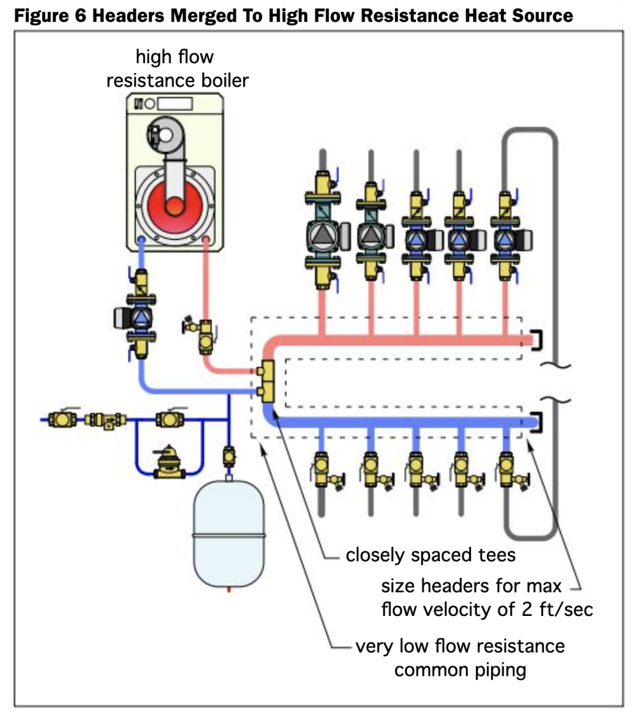
The pair of closely-spaced tees hydraulically separate the boiler circulator from the circulators on the header. Thus, the overall piping assembly within the dashed lines, (i.e., the common piping) has low head loss. Voilà: hydraulic separation between all circulators in the system.
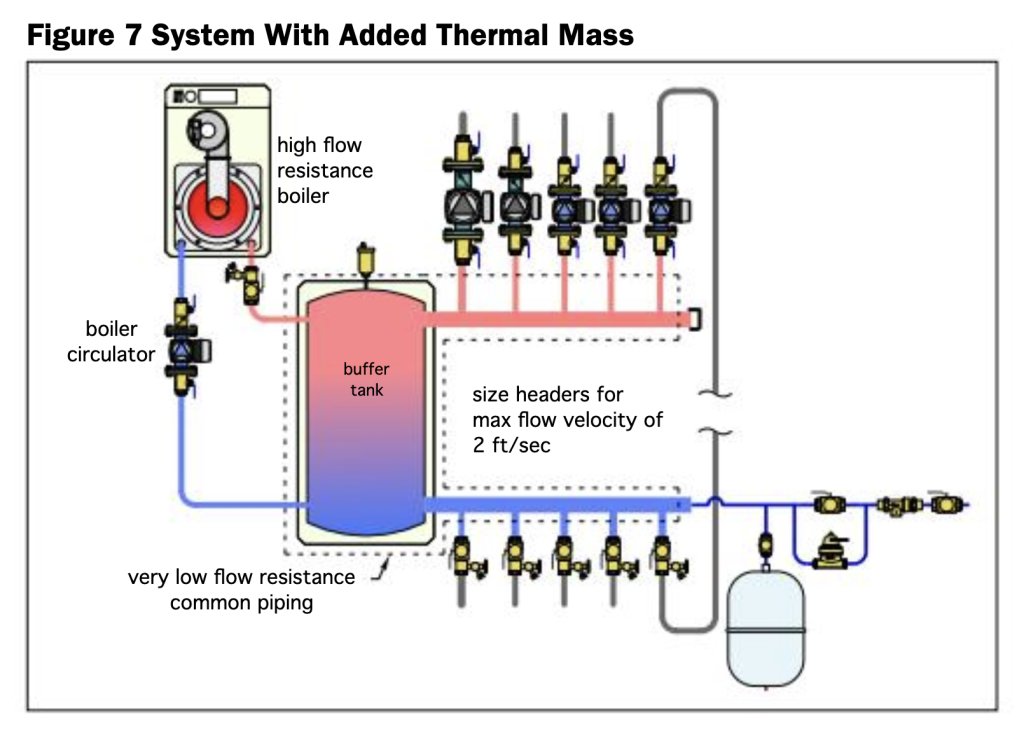
If your system needs added thermal mass to stabilize a low mass heat source against the potential demands of a highly-zoned distribution system, then let a buffer tank, (piped as shown in Figure 7, and working in combination with the short/fat headers) provide the hydraulic separation.
Finally, it is possible to use a component called a “hydraulic separator” to provide – you guessed it – hydraulic separation. The piping is shown in Figure 8.
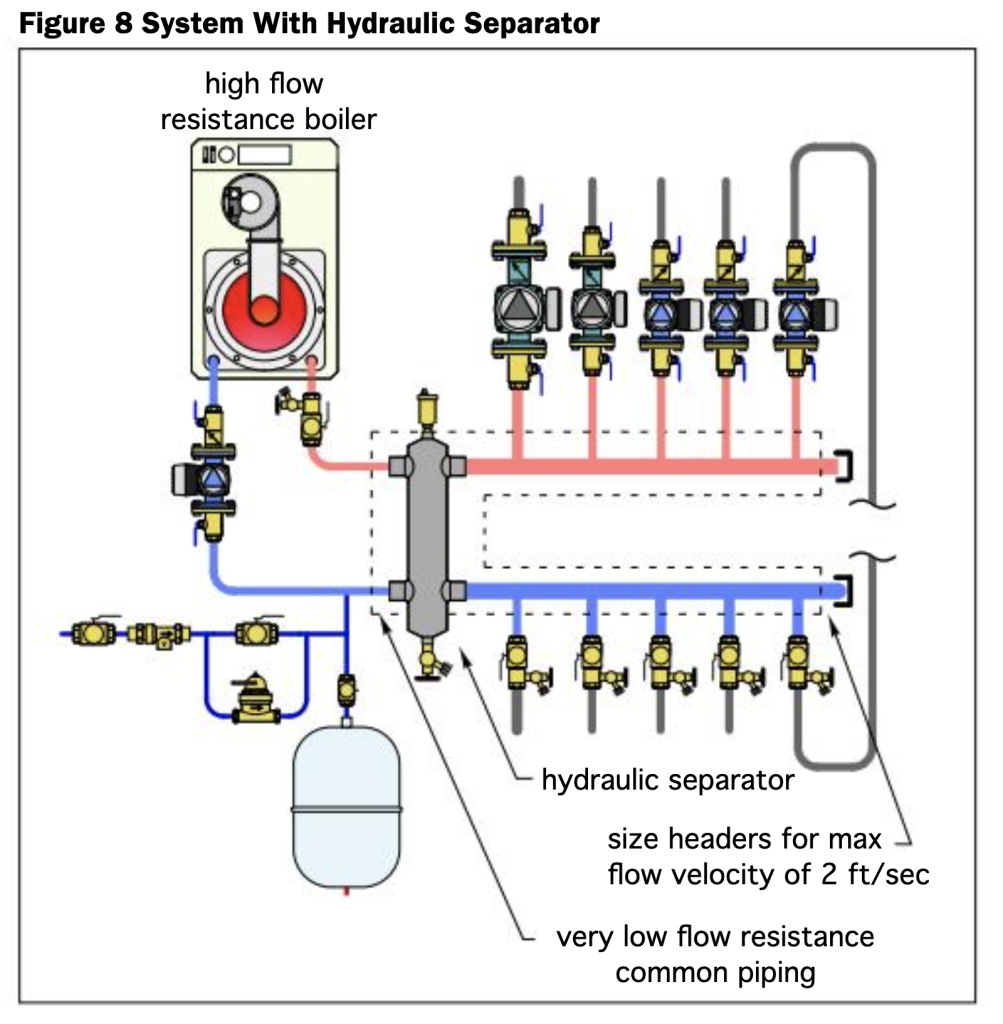
Along with hydraulic separation, many hydraulic separators now contain internal screens called coalescing media. These inserts enhance the ability of the hydraulic separator to separate microbubbles of air passing through the upper portion of the separator. Using a hydraulic separator with a coalescing media eliminates the need to use a separate, high efficiency air separator in the system.
A second coalescing media, built into the lower portion of the hydraulic separator, enhances its ability to trap dirt particles that might be riding along with the flow as it returns from the distribution system. With multiple passes, some coalescing media can separate out dirt particles as small as five microns. They drop out of the active flow path and into the lower portion of the separator. A periodic opening of the valve at the bottom of the hydraulic separator can flush out this dirt.
FOURSOME
There you have it: four methods of achieving the very desirable characteristic called hydraulic separation in your hydronic systems. Notice that all these methods provide the same supply water temperature to the loads and that none of them require a dedicated primary loop circulator. In that respect, the methods shown, in my view, are significant improvements over traditional primary/secondary piping. Integrate them into your designs where appropriate. <>

John Siegenthaler
