
When to use a three-pipe buffer tank configuration
November 5, 2018 | By John Siegenthaler
When it comes to thermal storage tanks, there are many shapes, sizes and pressure ratings available, ranging from tanks that resemble (or are) domestic water heaters to larger ASME-certified pressure vessels.
In most hydronic thermal storage applications, it is desirable to maintain temperature stratification within the tank–that is hottest water at the top, coolest water at the bottom. Good stratification improves the “quality” of thermal energy available from the tank, relative to that available from a full mixed tank.
A thermal storage tank, left undisturbed, will naturally stratify. The temperature range from top to bottom will depend on several factors, including:
• The height to diameter ratio of the tank
• The thermal conductivity of the tank walls
• The insulation used on the tank
Conductive/convective heat loss through piping connected to the tank
Thermal stratification should be maintained within the tank while heat is being added from the heat source(s), as well as when heat is being extracted by the load(s). The degree to which this happens depends upon the temperature rise across the heat source, and the temperature drop across the load circuits.
Ideally, the water returning from the load to the thermal storage tank should enter the tank at a “strata” that’s at the same temperature as the returning water. This minimizes buoyancy induced mixing within the tank. Flow should also enter the tank horizontally and gently, again to minimize mixing within the tank.
The latter can be accomplished by keeping the flow velocity entering the tank no higher than two feet per second, and connecting the piping to the side of the tank rather than the top or bottom.
What’s difficult is attempting to maintain a match between the temperature of water returning from the load, and the water temperature within the tank at the connection point. The temperature returning from the distribution system is going to change from when the load starts operating to when warm water makes its way through the load and start flowing back to the tank. The return temperature is also going to change as the supply water temperature changes.
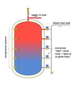
Figure 1
EURO-DETAILING
Outside of North America, some European designers have attempted to create “smart” return systems using multiple return valves as shown in Figure 1. These designers tend to also sell motorized valves.
A controller measures the return water temperature and the temperature stratification within the tank. As the returning water temperature varies, the controller opens one valve to allow water back into the tank where the internal temperature–either measured or inferred–is closest to the returning water temperature.
While this might be a control engineer’s delight in terms of hardware and algorithms, it adds expense and complication.
Another approach is to use a “stratification lance” within the tank. Water returning from the load enters an isolated chamber at the bottom of the storage tank and slowly rises through a polymer tube with lots of holes along its height and up the centreline of the tank.
In theory, the water rises due to buoyancy until it matches the temperature of the water in the tank. It then flows out of the central tube and into the tank with minimal disturbance of stratification. The holes are covered by small plastic flaps, which are designed to close to prevent circulation between the water in the central tube and water in the tank when the tank is at rest. As a result, there are no inflows or outflows.
While I am confident this approach has validity, I am not as confident in a more than 20 year life expectancy for the polymer tube, or the plastic flaps covering the holes on this lance, especially if that tank is exposed to water temperatures approaching 200F.
A SIMPLER APPROACH
My proposition to the challenge of maintaining reasonable stratification within the tank is three-fold:
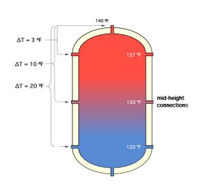
Figure 2
1. The hydronic industry needs thermal storage tanks with at least one generously sized mid-height connection point, as shown in Figure 2. This would be in addition to connections on the upper and lower sidewalls. A mid-height connection point offers the designer options as to where the return piping from a load can be connected to the tank.
If the mid-height connections are not needed for piping, they can be used for temperature sensors, thermometers or other instrumentation. These connections can also be plugged if they are not needed.
I would rather specify a tank with extra connections than try to “shoehorn” the design around a tank with not enough connections, or with connections in the wrong location on the tank.
2. All connections other than those specifically intended for an air vent or drain valve should have generously-sized connections. This allows use of larger pipe sizes near the tank to reduce inlet flow velocity and help maintain temperature stratification. I suggest a minimum of two-inch FPT treaded connections on tanks intended for residential and light commercial applications. Tanks for commercial applications should have a three-inch pipe, minimum, on all in-flow and out-flow connections. Large connections can always be reduced to fit smaller piping using relatively inexpensive bushings.
3. Designers need to assess the likely temperature drop of load circuits, then lay out piping that returns water from those loads into the tank at a level where the temperature in the tank is about the same as the incoming water.
If the load is likely to produce a “wide” temperature drop it can be returned to the lower sidewall connection. If the load will have a small temperature drop, it could be returned to the mid-height connection. If the load is small with a low Btu/hr heat transfer and operates with a minimal temperature drop, it could even be returned to the upper sidewall connection of the tank. These options are illustrated in Figure 2.
This concept is easy to understand, but not as easy to execute. The complication is that the return water temperature from any given load will vary as that load starts and operates. The temperature profile within the tank is also going to vary as heat is removed and when heat is added from one or more heat sources.
In practical terms, it is likely the load with the deepest consistent temperature drop will tend to set up a corresponding temperature profile within the tank. It makes sense to connect that load over the full height of the tank. A load with perhaps half that temperature drop, but the same supply temper-ature requirement, could then be piped over the upper half of the tank, assuming there’s a connec-tion port at that location.
WATCH OUT FOR THIS ONE
An example of where returning water from the load to higher connections on the tank makes sense is when a typical indirect water heater is supplied from the system’s thermal storage tank.
The internal coils in many North American indirect water heaters are, in my opinion, too small for efficient heat transfer at coil inlet temperatures below 180F. While it is possible that some thermal storage tanks can reach these high temperatures, it is usually the exception, especially with heat sources such as solar thermal collectors. Still, there is energy available for domestic water heating when thermal storage temperatures are as low as 125F, assuming domestic hot water delivery temperatures of 115 to 120F.
Heat can be transferred from thermal storage to the indirect tank as shown in Figure 3.
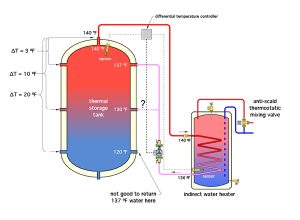
Figure 3
A differential temperature controller monitors the difference between the temperature in the upper portion of the thermal storage tank and the water temperature in the lower portion of the indirect tank. When the temperature of the “source” sensor in the thermal storage tank is at least 15F or more above the temperature of the sensor in the lower portion of the indirect tank, a circulator turns on to move heat from the former to the latter. When the thermal storage temperature is 10F or less above the indirect tank temperature, the circulator turns off. The “on” and “off” differentials can be adjusted based on the heat transfer performance of the coil heat exchanger and the position of the sensor in the indirect tank (e.g., lower placement of the sensor may allow for slightly lower “off” differential).
The issue I have experienced with this setup is that the rate of heat transfer from the coil heat ex-changer in the indirect water heater drops off considerably as the thermal storage tank temperature decreases. This results in minimal temperature drop across the coil. If the water leaving the coil is then returned to the lower connection on the thermal storage tank, it is likely to be significantly warmer than the water in the tank at this location. This induces buoyancy differences, which tend to break up tank stratification.
One way to reduce this effect is by bringing water back into the upper portion of the tank–no lower than the mid-height connection and possibly even to the upper sidewall connection. The latter is the better choice if the DHW load is small and the thermal storage tank can adequately supply space heating at lower water temperatures.
Although this is still not an ideal solution, it is an improvement over returning the water to the lower connection on the thermal storage tank.
SMARTER TANKS
In the future we may see improved methods for returning water from heating loads to thermal storage with minimal disruption of stratification–perhaps an intelligent device that can “unload” return water over the full height of the tank, so that it flows into a “strata” at the same temperature. The device will have to be robust to survive the environment within the tank for many years. Put your thinking hats on for this one.<>

John Siegenthaler
John Siegenthaler, P.E., is a mechanical engineering graduate of Rensselaer Polytechnic Institute and a licensed professional engineer. He has over 34 years experience in designing modern hydronic heating systems. Siegenthaler’s latest book is Heating with Renewable Energy (see www.hydronicpros.com for more information).
