
Top five new residential gas furnace tests
December 11, 2019 | By Ian McTeer
"We owe it to our customers and to the environment to be sure that newly installed gas appliances will operate at peak efficiency."
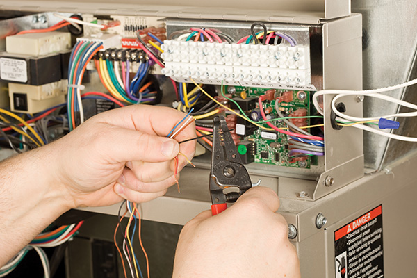
Image: Getty
Climate activists have made it clear that installing new natural gas and propane fired residential heating equipment, including cook stoves, fireplaces and water heaters, will become a thing of the past before long. Already several municipalities in North America have placed bans on future installations of residential gas utilities while also declaring climate emergencies related to excessive carbon emissions from burning fossil fuels.
Once North America’s electrical generation capacity and distribution grid have been restructured to accommodate all the power that will eventually be needed, all-electric HVAC/R will be our future. However, according to statistics from the Air Conditioning, Heating & Refrigeration Institute (AHRI), year to date shipments (as of August 2019) of residential gas furnaces increased 5.9 per cent over the same period in 2018. U.S. factories shipped 2.29 million units, up from 2.16 million in August 2018. Even oil furnace shipments are up 14.9 per cent with 21,949 units moved into distribution since August 2018.
Gas furnaces are, arguably, one of the lowest-cost heating options for many homeowners in the replacement market and in new construction. Single zone systems can be made efficient and comfortable when proper design, installation and commissioning techniques have been utilized. We owe it to our customers and to the environment to be sure that newly installed gas appliances will operate at peak efficiency.
There are five critical tests that should be taken at start-up to verify any given unit is operating in accordance with the manufacturer’s installation instructions and industry standards. Let’s look at them one by one:
- Gas pressure/Meter clock
- Line & Low voltage
- Flame signal
- Temperature rise
- Vent system pressure
Gas Pressure
There are three gas pressure tests that should be performed at system start-up or whenever combustion-related service problems occur. According to code, CAN/CSA B149.1 – 15, paragraph 6.3.2, “a piping or tubing system supplied at pressures up to and including 14 in w.c. shall be designed to prevent the loss in pressure between the appliance and either the termination of the utility installation or the last-stage regulator from exceeding the maximum allowable pressure drop specified in Table 6.1.”
Table 6.1 says that for natural gas or propane installations using a piping or tubing system with a supply pressure 7 in w.c. to 14 in w.c., the maximum allowable pressure drop is 1 in w.c. This is the standard pressure rating for residential gas pressure regulators. Gas utilities typically set-up the gas pressure regulator to provide a minimum of 7 in w.c. Propane supplier’s set up the second stage regulator to give fuel at 11 in w.c. and must not drop more than 1 in w.c.
To test for allowable pressure drop, do the Static and Working pressure tests:
a) Gas line Static Pressure test:
- Turn off the gas supply to the furnace.
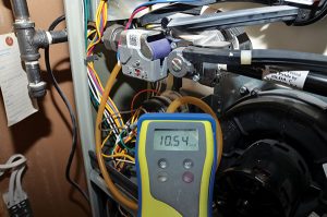
Static pressure, appliance not operating
- Install a pressure tap into the line side of the gas valve. Some valves have raised pressure taps that simply require loosening of the tap set screw one quarter turn. A gas resistant hose is then placed over the tap and connected to a manometer.
- Once the manometer is connected, turn on the appliance gas supply. Do not start the appliance.
- Read the manometer: Let’s say the manometer reads 10.54 in w.c. on an LP system start-up. This is the Static Pressure with no gas appliances in operation.
b) Working Pressure Test
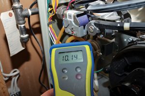
Pressure drops to 10.14 w.c. 1st stage
- Start the furnace; use a test mode if available on two-stage or modulating units.
- When the unit fires, note the new gas pressure and looking at the above example, it must not be less than 9.54 in w.c.
- Allow a two-stage unit or modulating furnace to achieve 100 per cent input. Again, the final stage must not result in a pressure drop. greater than 1 in w.c.
Static and Working pressure test proves the adequacy of gas supply pressure and will allow the furnace to operate according to the manufacturer’s specifications. The static test will also detect excessive line pressure caused by a faulty utility pressure regulator. Too much pressure will likely damage the gas valve but it could also cause a potentially dangerous delayed ignition rough start.
c) Manifold Pressure
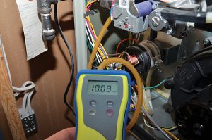
At 100 per cent input, pressure drops to 10.08 in. w.c.
Contrary to popular belief, manufacturers do not set up the final manifold pressure on most residential gas furnaces. Often the pressure is set to allow test firing on the assembly line, typically something over 3 in. w.c. for natural gas furnaces. Final pressure setting must be done on the job and 3.5 in w.c. is not always the required pressure. Some units require natural gas at 4.0 or 4.5 in. w.c. in the manifold. Two stage units typically fire natural gas at 1.4 to 1.7 in. w.c. on first stage. Be sure to follow the manufacturers manifold gas pressure set-up instructions carefully. Record the static, working and manifold pressures for posterity. Be sure to clock the gas meter for evidence the unit is consuming the correct quantity of fuel.
Voltage
Electronic controls are voltage dependent, improper voltage elicits devilish responses from circuit boards, sensors and related controls. Residential gas furnace manufacturers typically specify a nominal voltage ranging from 110 VAC to 120 VAC. Voltage fluctuations affecting proper appliance operation do occur for several reasons such as undersized branch circuit wiring or voltage transients. At start-up, just like gas pressure, static and working pressure tests take a voltage reading at the circuit board Line Hot and Line Neutral spade terminals. If your manufacturer publishes a nominal line voltage input of 120 VAC, the measured voltage at rest could be allowed to fluctuate as much as +/- 10 per cent.
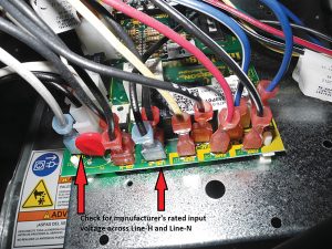
Take a voltage reading at the Line Hot and Line Neutral spade terminals.
Remembering that both low voltage and excessively high voltage will cause anything from erratic operation to very expensive damage, the measured voltage should be reasonably close to the manufacturer’s published nominal value. Take a second—or working—voltage reading once the fan motor has started. Ideally, there should be almost zero voltage-drop. Be sure to check for voltage across the Line Neutral terminal and chassis ground. Control boards needing a properly made earth-ground for a zero-volt reference could lock-out or cause erratic operation if there’s more than 2 volts on ground. Some voltage issues are related to the homeowner’s electrical supply and will require a certified electrician or a utility representative to investigate voltage spikes, transients and grounding issues.
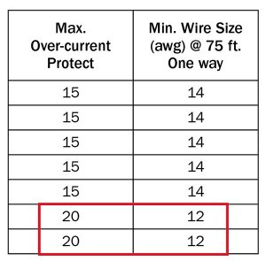
Table 12: gauge wire required for large model
Gas furnace manufacturers also publish branch circuit wire sizes that should be used in order to provide a safe path for electrical current to be consumed by the appliance during operation. Larger input gas furnaces such as 100K and 120K Btu/hr models with blowers capable of handling up to 5 tons of cooling require heavier wire and larger circuit breakers. The old blister being removed might have been rated for service with 14-gauge wire on a 15-amp circuit breaker. Connecting the new appliance using the existing wire and breaker could cause excessive voltage-drop and might even be dangerous. The manufacturers table (to the right) requires 12 gauge wire be used with the two largest models.
Finally, measure the transformer’s low voltage output, static and working. If the voltage reading is ever less than 20 VAC or more than 30 VAC across “R” to “C”, expect erratic operation.
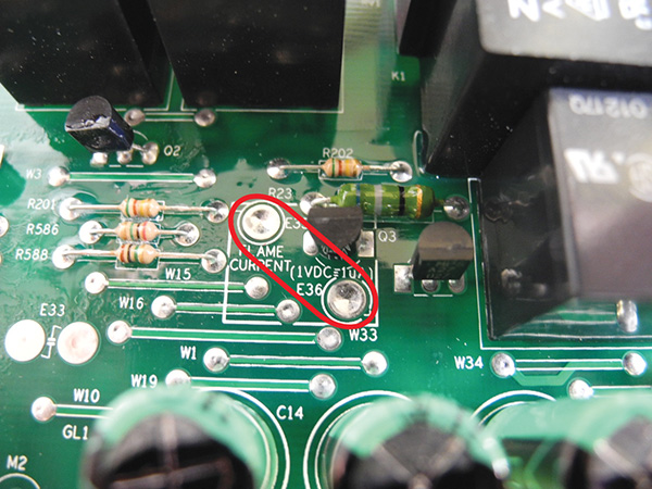
Measure flame signal during operation using a voltmeter set on the DC scale.
Flame Signal
One of the most overlooked causes of erratic gas furnace operation has to be ignition lock-outs caused by a poor flame signal. This can happen for a variety of reasons: damaged or misaligned flame rod (maybe the appliance was damaged during shipment or installation), voltage problems, gas pressure problems, pinched wiring and so on. Admittedly, in days of yore, checking the flame signal wasn’t always easy. Fortunately, newer controls have solder pads incorporated onto the board so that simply touching the leads of an accurate voltmeter set on the DC scale to the pads will indicate the flame signal during operation.
Thus, 1 volt DC = 1 µA. A newly installed gas furnace should be producing a flame signal somewhere in the region of 2.5µA to 3.0µA. Some control boards will report-out a low-sense flame signal at 1.25µA by flashing a blink code on the control board’s diagnostic LED. Be sure to record the Day 1 flame signal for future reference.
Temperature Rise
Properly ducted forced warm air furnaces will provide decades of reliable service provided they run not too hot, not too cold, but just right. Once done with gas pressure tests and a meter clock has verified fuel input, allow the unit to run for at least 10 minutes before taking a temperature rise. Air temperature should be measured in the trunk ductwork and out of the line of sight of the heat exchanger to prevent radiant heat from skewing the numbers.
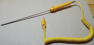
TypeK thermocouple probe
Return air entering temperature is taken at the entrance to the blower compartment. Use a Type K thermocouple or equivalent probe designed for measuring air temperatures. The probe, pictured left, is ideal for residential ducts being long enough to get a good representative air temperature sample using a mini traverse.
All gas furnaces must operate within the manufacturer’s specified temperature rise range. Manufacturers provide charts indicating the correct range for any given model, or the charts may indicate a more precise temperature rise at the rated air flow level.
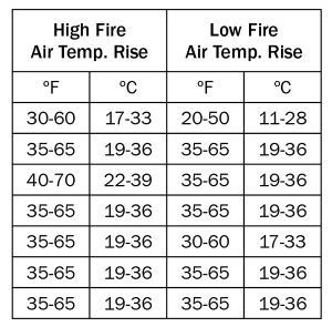
Manufacturer’s Temp-Rise chart
For example, in the chart to the left, this manufacturer provides a rise range for each given model. I have removed all the model numbers, but suffice to say there are seven models of two-stage gas furnaces covered.
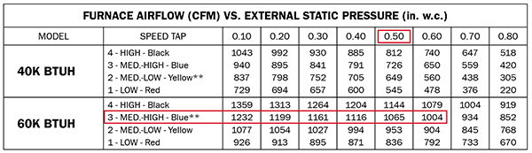
Another manufacturer provides two charts. The first chart (below) lists airflow versus external static pressure. I have removed the model numbers and shown data for the two smallest units:
The chart indicates the 60K Btu/hr unit comes with the blower speed factory set on the medium high speed and the blower will deliver 1065 cfm of air against 0.50 in w.c. of external static pressure. The second chart (below) indicates the exact temperature rise that should be measured if the furnace is moving at least 1000 cfm of air.
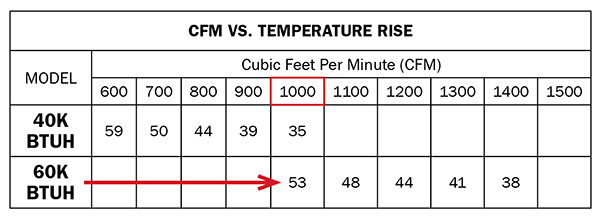 Thus, at 1000 cfm of air the temperature rise should be 53F. Since the blower’s factory setting should be delivering at least 1000 cfm, a temperature rise measurement of 60F, for example, would be unacceptable and likely indicates a serious distribution system problem. If this happens, that problem must be identified and repaired before leaving the homeowners alone with their new furnace.
Vent System Pressure
After gas pressure testing is complete, tee a manometer into the vent system pressure switch tubing. When re-starting the unit for the temperature rise test, take note of how much negative pressure the draft inducer can create. This number should be compared to the manufacturer’s minimum requirement for continuation of the combustion cycle.
Typically, with a properly installed vent system containing a minimal amount of moisture, the deep negative should be significantly below the required closing pressure. After the temperature rise test and the limit control function has been verified (allow at least 10 minutes of 100 per cent input operation), restart the unit and take note of the new deep negative closing pressure. It’s likely to be higher (closer to zero) but still lower than the manufacturer’s requirement. This test will verify vent system sizing (pipe size, length and elbow count) and that moisture is draining adequately. See the sidebar (page 20) for more information about checking vent pressure.
Data collected from these five tests plus any other operational details should be documented in an easily accessible method that becomes part of the installation. Start-up data belongs to the heating system, not the contractor nor the homeowner.
Start-up information forms a vital part of any unit’s operational history and will be of great benefit to technicians during future service calls. A lifetime’s worth of service history will eventually provide the criteria necessary in making equipment replacement or repair decisions. ∆
VENTING SYSTEM CHECK
Following is a review of items to check to ensure proper venting of the new gas furnace:
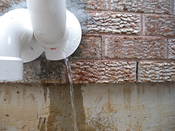
After at least 10 minutes of operation, the vent system will start to fill with water. Accumulated water must be able to flow back toward the furnace and out through the drain.
Your manufacturer may require that the drain trap be filled prior to checking the gas manifold pressure.
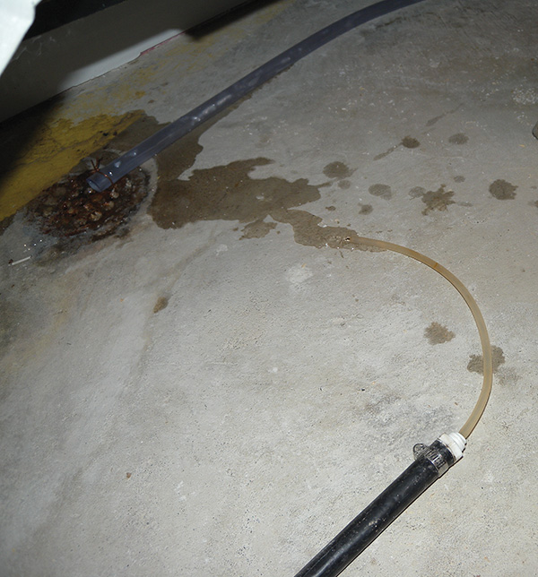
Condensate drain line must be free-flowing: no restrictions allowed!
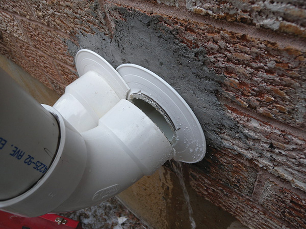
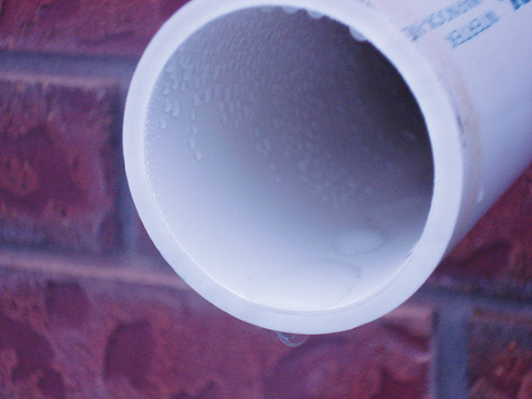
Improperly installed vent systems happen far too often
Water accumulating in an improperly installed vent will eventually trip a pressure switch creating a no heat situation. This failure happened in January, more than a month after initial installation.
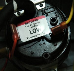
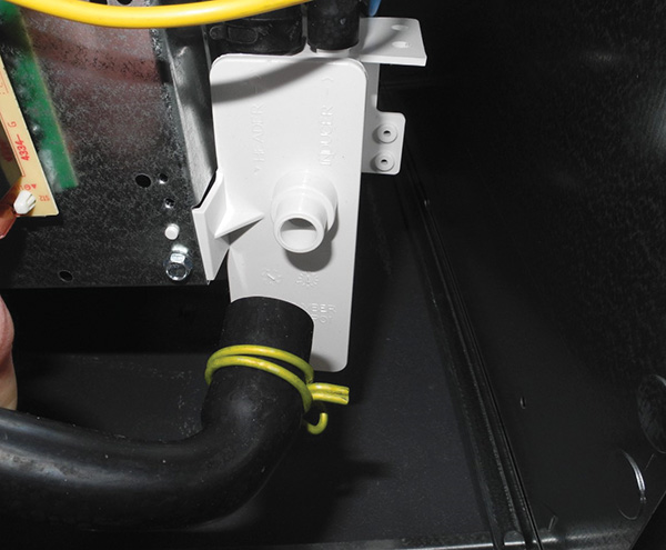
Check with your manufacturer, know how much deep negative pressure is required to close each pressure switch throughout their model line. The first stage pressure switch pictured above closes at -0.97” wc. After the unit fires, pressure will increase (move toward zero) but must not rise beyond the rated pressure for any given pressure switch. Printed on this label is the operating pressure -0.88” wc. This switch has a +/- range of 0.04” wc. During operation a tech might measure anywhere from -0.84” to -0.92” and still be within normal operating range. If the vent system pressure is within range, then the venting system is properly sized and sloped. Condensate will freely run to the floor drain or condensate pump.
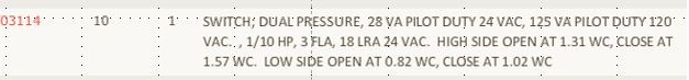
Typical manufacturer data of a dual pressure switch set-up providing a part number along with opening and closing pressures for each switch. The operating pressure will be printed on the label of each switch.
Ian McTeer is an HVAC consultant with 35 years experience in the industry. He was most recently a field rep for Trane Canada DSO. McTeer is a refrigeration mechanic and Class 1 Gas technician.

