
Troubleshooting pointers for commercial pumps
December 18, 2016 | By Mike Miller
When troubleshooting commercial pumps it is always important to note the type of symptoms, the point at which the symptoms began and the time period over which the symptoms developed. In particular, consider whether something changed in the system prior to the noted symptoms and performance issues.
While there could be several other symptoms, causes and resolutions, this article will cover some of the more common, yet simple reasons for issues that may be resolved without major work.
Symptom: mechanical seal failure
Mechanical seal failure is the most common component failure in a centrifugal pump as the seals are a wearing component and over long-term pump operation they will eventually fail. There are a number of reasons why a mechanical seal can fail prematurely and because they are a wearing component, seals are generally not covered by manufacturer’s warranty.
Mechanical seals typically fail prematurely due to either excessive heat or debris in the fluid. In the case of excessive heat this is often the result of the seal running in air without the benefit of the pumped fluid cooling it and providing a hydrodynamic film across the faces. The most common reason for this is that air was not properly purged from the pump, or perhaps the pump was started dry to begin with.
Most commercial pumps allow for air removal mechanically right at the pump volute near the seal location, so that this could be eliminated prior to start-up. Fluid quality is the other common reason for seal failure. The system should be flushed properly to rid of any unwanted dirt and materials inside of the piping prior to fitting the pump and startup. To eliminate fluid quality and air as possible causes of seal failures, it is always best practice to follow the manufacturer’s startup procedures and to install dedicated air and dirt removal devices in the mechanical system.
There are several different manufacturers of very effective air and dirt removal devices. Most would feature some form of micro air bubble removal system internally that would allow the removed air to collect internally and rise to the top of the vessel. There is often an air vent at the top utilizing a floating seal so that air escapes, but fluid is kept within the system. This same device separates dirt from the fluid. The dirt then falls to the bottom of this tank where it could be flushed out periodically as part of regular maintenance of the system.
Additional potential reasons for premature seal failure include vibration within the pump assembly caused by pump imbalance (due to improper installation), improper alignment of the coupling (any base mounted pump), or improper selection of the pump for its duty point when operated too far to the right or left of the Best Efficiency Point (BEP). While these reasons do not always cause an immediate seal failure, they can certainly shorten the seal’s service life.
In variable flow applications where drives regulate the speed of a pump, attention must be given to the pump
manufacturer’s minimum speed recommendation. It is wise to keep the minimum speed at 20hz or greater to ensure adequate flow of fluid over the seal’s surface is maintained to allow it to cool and to provide the needed lubrication to maintain the seal surfaces intact.
Symptom: pump too noisy
It is important to note where the noise is coming from and what type of noise it is? Is it mechanical, that is metal-to-metal contact, or hydraulic, that is fluid at high velocity? Is it from the motor? It could be a failing bearing within the motor or it could be caused by improper alignment of motor and pump (mostly base mounted pumps), causing unnecessary strain and pressure on the pump’s impeller and shaft. It is always advised that any base mounted pumps are verified for alignment prior to starting operation of the pump. The piping itself could cause additional strain on the pumps. Perhaps the pump was fitted into an existing piping network and had to be squeezed into the available piping? Best practice in the field to follow to eliminate this type of strain, is to place the pump first and then to pipe away from it, rather than to it. Also, ensure adequate piping support is in place.
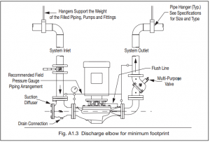
Figure 1 Piping arrangement with the inclusion of a suction diffuser and triple duty valve. Most pump manufacturers have a connection for a pressure gauge available on both the suction and discharge side of the pump
Noise could be also caused by air or turbulence in the system. If an air and dirt separator is installed in the proper location in the system, then air is not likely the cause. Turbulence in the suction piping can be caused in systems if a recommended suction diffuser is not installed on the pump’s suction side as per installation instructions or is missing altogether. If no suction diffuser is used, make sure there is a minimum of five to 10 pipe diameters of pipe between the closest elbow and the suction side of the pump as recommended by the pump’s manufacturer. This will ensure there is no turbulence entering the pump.
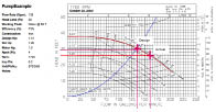
Figure 2 Sample pump performance curve of selected pump for 135 GPM flow at 30 ft/hd at design duty point
Is the pump providing too much flow, or perhaps too little? Velocity could be the cause of noise. Find out where the pump is operating. Does this tie into other performance-related symptoms, such as too little or too much of a system temperature differential (deltaT)?
Symptoms: too little or too much flow/system deltaT
Any constant or variable flow system pump can only operate on its performance curve. Understanding those performance curves and making use of pressure gauges, one on the suction side and one on the discharge side of the pump, can help identify what is the present performance, good or bad.
In order to identify actual system resistance at any time, one can take the pressure differential across the running pump in psi and convert that to feet of head (ft/hd) resistance by multiplying it by 2.31. Would the pump be operating perfectly at the designed duty resistance of 30 ft and at 135 GPM, the pressure differential would be roughly 13 psi (13 psi x 2.31 = 30 ft/hd). When this is compared to the pump performance curve and verified with a HP reading, one can determine if the pump is indeed operating where it should be.
Calculation of HP:
HP = (V * a * e) / 746
Where:
HP = Horsepower
v = Voltage
a = Full Load Amps
e = Efficiency
As an example, if the pressure differential across the pump is read at 12 psi, then the actual system resistance would only be (12 psi x 2.31) 27.72 ft/hd. When this is compared to the pump performance curve and verified with the HP reading, then it would be indicating that the actual flow is closer to 160 GPM instead. The result could be velocity noise. Too much flow means the pump is running out on the curve because the actual head is lower than the design head. Having the ability to throttle the multipurpose valve installed after the pump allows for additional artificial resistance to be created. This in turn will back the flow up on the performance curve and return to what was calculated as the design head and therefore pump performance.
If the opposite is found and the actual system resistance is greater, then of course the flow would be insufficient to meet the design flow. In this case it could be that the pump is undersized due to additional system resistance caused by something external to the pump itself. Could it be that a valve downstream is throttled back too much, or even closed?
Additional pump performance challenges could be caused by miss-wiring of a three-phase motor. This could be verified as per the above, but the noted HP is way off from where it should be (i.e. lower). Check the motor’s rotation direction and compare it to the manufacturer’s instructions. Just having one set of the legs reversed can cause the impeller to spin backwards. The noted system symptoms would indicate that the system flow is too low while the pressure differential across the pump suffers also.
There are other possible reasons as to what could be going wrong with a pump, but the scenarios discussed here are among the most common system issues we come across.
Mike Miller is past chair of the Canadian Hydronics Council (CHC) and director of sales, building services Canada with Taco Inc. Miller can be reached at
hydronicsmike@taco-hvac.com.

