
Unintended Consequences
September 8, 2020 | By Robert Bean
This case study illustrates the impact architectural changes can have on mechanical system design.
Over my career I have been fortunate to work with some great clients and design and construction teams where the relationship was not just about completing a successful project but also about education—that being the exchange of knowledge that one earns from challenging events.
Any seasoned practitioners will tell you it is ‘project pain’ that provides the experience and any pleasure after that is just a bonus. The following case study is an example of a terrific client, an excellent team and a project with some interesting moments.
The Project
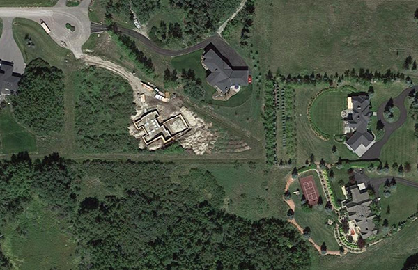
The 7,800 sq.ft. home (Figure 1) borders between climate zone 6 and 7 with a winter design temperature of -35F (-37C) and summer at 85F (30C). It had several common indoor environment quality (IEQ) challenges, initially including a six-burner gas range, a 6-ft. (1.8m) gas fireplace in a great room that had a bank of windows extending 20 ft. (6m) up from the floor, a gym and an attached garage that was big enough that it initially required CO monitoring.
Several rogue zones had thermal comfort concerns due to large window-to-wall ratios and air quality concerns due to the attached garage, fireplace and kitchen range combined with the required large exhaust hood. The latter adding a potential noise issue.
The five-person family reached out to us after an online search for healthy indoor environments introduced them to our website and services. After our introductory interview, project questionnaire and initial site meeting, it was clear our project values would work together.
We set out expectations and deliverables, which included consultation on the architecture, enclosure and HVAC design. Our thermal comfort and air quality targets were guided by ASHRAE Standard 55, and a mix between ASHRAE 62.2 and CSA F326.
We also conducted solar control and daylighting with several discussions on external shading, window characteristics and performance.
Design Version 1
From these initial discussions and agreement on critical enclosure improvements, our load calculations resulted in a dead-simple single low-temperature hydronic heating system (Figure 2) with reset using only the boiler controls and with only one circulator for the system and non-electric thermostatic control valves for room control.
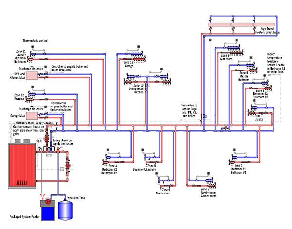
Figure 2
It does not get much easier for such a large home. The harmonized temperature was established by manipulating floor tube spacing where possible, increasing radiant surfaces in rogue zones using wall space under windows (Figure 3, below), adding a trench heater for the great room, and increasing the surface area of the makeup air coils. This approach is preferred over a multi-temperature system, which adds more costs for controls and circulators, commissioning complexity and future maintenance issues for the owner.
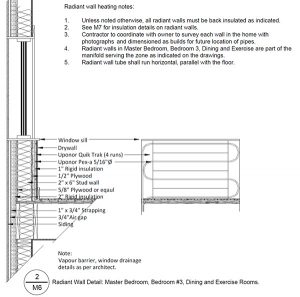
Figure 3
At least this was the plan until what was discovered after approval for construction drawings were issued. During a site visit, it became apparent that the specified exterior insulation and radiant walls had been omitted, and additional windows had been installed.
Design Version 2
As any professional practitioner can attest, such deviations from a stamped design is not a minor event. We advised there would be heating and cooling load penalties on most zones requiring a complete system redesign.
After getting approval for the additional engineering fees, we developed design version 2 (Figure 4, below). The consequences from the revisions resulted in the very system we had tried to avoid initially. The new calculations revealed a need for more complicated systems with multiple temperatures, which meant electronic controls and more circulators and a redesign on the partially installed distribution piping system.
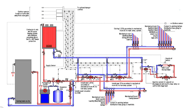
Figure 4
It also meant an increase in the heating plant and cooling equipment and distribution piping. We did not do a post-change cost analysis, but I suspect between our fees, the increase in capital costs, including the service fees from the installer, would have paid for a big part of the omitted insulation.
Indeed, any balance would have been quickly offset by lower operating costs relative to the now higher loads.
The client was entirely professional about the hick-up, as were the trades, which helped make the changes flow without any conflict.
Ultimately the real consequence for the project is an increased load profile and more complex system. Fortunately, the final piping assembly was done the way I like them, plumb, parallel, level, and square (Figure 5).
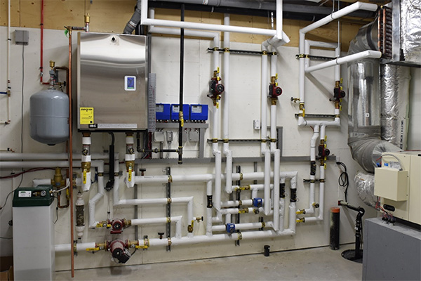
Figure 5
Challenges/unique solutions
Our ASHRAE Standard 55 assessment of several rooms, and specifically of the great room, showed potential for drafts, radiant asymmetry, and mean radiant temperature (MRT) issues due to the large bank of windows.
Our year-round solution, in addition to radiant floors, was to place a hydronic trench heater directly in front of the patio doors (Figure 6).
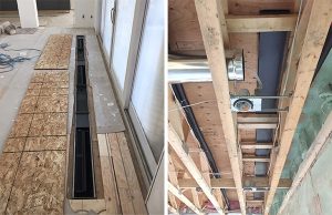
Figure 6
In the winter, this would provide a warm curtain of air to stop the downdraft, warm the glass and improve the asymmetry. Also, a preheat coil on the HRV/kitchen exhaust make up air unit could be used for supplemental heat.
For cooling, we used a ducted mini-split and fed its cooled air into each end of the trench heater, and we used its linear fans to boost the airflow up the glass (Figure 7). This cooled the inside surface temperature of the glass, reducing the asymmetry and MRT issues.
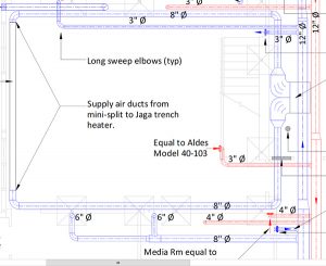
Figure 7
In combination with elevated airspeeds from a large ceiling fan, the room fell within compliance with ASHRAE Standard 55.
Next up was how to provide up to 800 cfm (378 l/s) of kitchen range exhaust with makeup air, and up to 400 cfm (189 l/s) of home ventilation air with a single air handler.
In either operation, the sound from airflow had to be minimized. Our kitchen exhaust solution was an inline direct drive exhaust fan with silencers on the inlet and outlet. The fan was located about 20 ft (6m) away above the range in the attic space. A strategy I have used many times with excellent results (Figure 8).
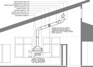
Figure 8
The building ventilation was a multi-speed HRV whose exhaust fan was disabled by controls when the kitchen exhaust fan was on (Figure 9). Thus, without exhaust flow, the HRV became a makeup air unit.
Preheating the air in both modes was a generously sized glycol coil. Home ventilation ducting was designed for low velocities from 200 fpm (1.0m/s) up to 500 fpm (2.5m/s) and kitchen exhaust from 1000 fpm (5.0 m/s) up to 2000 fpm (10m/s).
The control solution is proprietary, but I will take this opportunity to strongly suggest that manufacturers of both kitchen exhaust fans and HRV’s develop an integrated solution for speed matching their products and disabling the HRV exhaust fan.
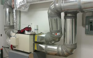
Figure 9
Closing thoughts
Through the integrated design process, thermal comfort, lighting, sound, and indoor air quality criteria should be first and foremost passive solutions.
Thus architecture, enclosure and interior design are the first solutions to indoor environmental quality challenges. These “three amigos’” when adequately designed simplify electrical and mechanical systems and their associated commissioning, maintenance, capital and operational costs.
Far too often energy conservation is ignored, forcing designers to unnecessarily use the brute force of energy in the form of heat and electricity to solve IEQ problems. There is also a failure to use design solutions like harmonizing fluid temperatures to the lowest common denominator to enable higher system efficiencies.
In this case, the original intentions were good but were destroyed by what was thought to be an inconsequential decision.
As we have said before…in design – everything matters.
***
Considering the current pandemic there are no words to describe how comforting it is knowing our engineering philosophy of ‘designing for people’ has left behind indoor spaces that are serving our clients with excellent independent and dedicated air quality and thermal comfort systems. For the naysayers of days past – I told you so…there – I said it! <>
***
For more on ASHRAE Standard 55, interested practitioners can obtain for no charge a new book on Thermal Comfort Principles and Practical Applications in Residential Buildings. This project was funded in partnership with BC Housing and can be accessed through this link: www.linkedin.com/groups/13843486/
 Robert Bean is director of www.healthyheating.com, and founder of Indoor Climate Consultants Inc. He is a retired engineering technology professional (ASET and APEGA) who specialized in the design of indoor environments and high performance building systems.
