
What to do about gas furnace ignition lockouts
February 24, 2021 | By Ian McTeer
Regular cleaning and maintenance goes a long way to ensuring fewer no heat calls and furnace lock outs.
(photo: Director/Getty Images)
The gold standard for reliable gas ignition and dependable operation of residential gas furnaces and water heaters, for many decades, was the standing pilot using a thermocouple to prove flame. Service technicians carried replacement thermocouples, a length of aluminum pilot tubing, sometimes a pilot burner assembly or two and a bunch of ferrules as standard truck stock.
Often times, cleaning combustion debris from the pilot burner assembly allowing the flame to properly envelop the thermocouple proved to be all the servicing needed. Service techs could install a thermocouple adaptor into the gas valve millivolt circuit, take a reading with a millivolt meter and determine the performance of the flame proving system based on adequate millivoltage output. Even today, taking the time to confirm the flame signal is always a good insurance policy providing some protection from ‘no heat’ callbacks.
Although very robust and reliable, the traditional standing pilot ignition system wasted large amounts of natural gas and propane. Just imagine subdivisions full of gas furnaces and water heaters running standing pilots 24-hours-per-day all year. Eliminating such waste in the name of energy conservation and improved efficiency proved to be a wise decision made by governments and manufacturers alike.
Standing pilot equipped furnaces are a thing of the past, but safely igniting an otherwise dangerous hydrocarbon fuel along with proving the presence of a sturdy flame continue to be the most important tasks of any ignition control system.
Types of Ignition Systems
The two main manufacturers of gas ignition control systems used with modern high efficiency residential gas furnaces are Honeywell and White-Rodgers. Here is a look at the ignition and flame proving characteristics of several types of controls manufactured by one or the other over the years:
Intermittent Pilot: Typical is the Honeywell S8610U Control Module VR8345 gas valve and a spark lit pilot assembly with flame rod. On every call for heat, the pilot is lit, and the pilot flame is proven before the main gas valve can open to feed the burner assembly.
Honeywell Smart Valve: Like Honeywell’s intermittent product except the pilot flame is ignited by a small hot surface igniter.
Direct Burner Hot Surface Ignition: Both Honeywell and White-Rodgers market this type of ignition system in which the main burner is lit directly by the hot surface igniter and flame is proven by a remote flame rod within a specific timing sequence.
Direct Burner Spark Ignition: A Honeywell system using its S87D ignition control along with a spark unit and a remote flame sensor.
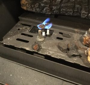
Fig. 1.
In the example (Figure 1, right), a spark lit pilot plays a flame on the flame rod and on the main burner. Flame is proven and main burner lights off. Pilot stays lit throughout the call for heat.
Furnace manufacturers using White-Rodgers ignition controls, for example, will install a silicon nitride hot surface
ignitor at one end of the burner train and mount a flame rod in front of the last burner in the train. Instead of proving a pilot flame, the remote sensor location at the far end of the train will generate a flame signal once the last burner is lit.
Flame Proving
Ignition control modules employing a remote flame sensor rely on a phenomenon known as flame rectification as proof that fuel delivered to the burners is alight. The phenomenal part of flame rectification has to do with the fact that as gas burns, electrons are released from the fuel molecules creating an ionized envelope around the flame rod. The flame then acts as path for electric current.
The remote flame rod is continually powered by the control board and is located within a specified distance from the gas burner. Once enveloped in the gas flame, AC current available at the flame rod can pass through the ionized envelope to ground by way of the burner head. Since the burner surface area is much larger than the flame rod, electron flow is greater in one direction than the other. (Figure 2)
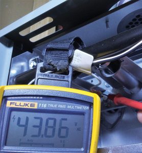
Figure 2. This White-Rodgers flame rod has approximately 45 volts AC to ground available as long as power is supplied to the furnace. Manufacturers specify the location and spacing of the ignitor and flame rod.
In the process, AC current is partially rectified into a pulsing DC signal that travels back to the control board through the chassis ground. Once the control board receives the pulsing DC signal within a specified time limit, it will allow the combustion process to continue.
Simply stated: the voltage source is the ignition control board; the “load” is the flame sensing circuitry inside the control board; the conductors are the flame rod and burner head; the flame allows the circuit to be completed.
Ignition Lockouts
The ignition sequence of a typical draft induced gas furnace is a highly regulated process. Once a call for heat has been received by the ignition control, it does an internal self-check (verifies limit switches are closed, pressure switches are open, no flame signal exists) and some boards will “exercise” board mounted relays.
Then, the draft inducer starts, and the board waits for one (or more) pressure switches to close thus proving adequate venting of combustion products will occur. The board then powers the hot surface ignitor, 20 seconds later the gas valve will open allowing fuel to flow to the main burners.
The board will only wait for five seconds to receive the partially rectified pulsing DC signal otherwise the gas valve will close.
The board will initiate an interpurge period keeping the draft inducer running for 60 seconds clearing out any unburned natural gas or propane from the combustion chamber and venting.
After interpurge is completed, the board will try two more times to establish a flame in the same manner as the first trial for ignition. If no signal is received after the third trial for ignition, the board goes into lockout for 300 seconds (five minutes). LED equipped control boards will typically flash a red LED two times indicating flame failure – retries exceeded.
Many generations of control systems have produced significant changes to ignition control board characteristics, for example, older White-Rodgers integrated furnace controls (IFCs) utilizing silicon carbide hot surface igniters often had 30-second pre-purge periods, and igniter warm-up times as long as 45 seconds in some cases. Some controls lock out for one hour but can be re-set by removing and restoring the 120-volt power supply.
IFC’s also have a “wait” state in which the draft inducer and main blower fan will run, literally waiting, until the problem is fixed. Service technicians need a wealth of information and experience in dealing with ignition lockout problems.
What causes lockouts?
I’m going to take a flying leap into the pool of potential no-heat issues and say that lack of maintenance is the number one reason for lockouts.
There is no such thing as clean combustion air, even outdoor air contains cosmic dust, thousands of tons of it fall to earth every year. Household air used for combustion also contains dust, sand particles, pollen, dander, furniture and carpet fibres not to mention corrosive chemicals such as:
- Permanent wave solutions
- Chlorinated waxes and cleaners
- Chlorine-based swimming pool chemicals
- De-icing salts/chemicals
- Cements and glues
- Paint remover and varnish
- Anti-static fabric softener
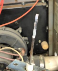
Figure 3. A typical dirty flame rod needing simple maintenance. (photo: Tony Jury)
As these particles and chemicals pass through the combustion process their residues are deposited onto the flame rod, starting a process of electrical insulation that eventually completely disrupts the flame signal (Figure 3).
The flame rod should be cleaned with a non-abrasive material such as fine steel wool or a plastic scrub pad prior to every heating season. Using sandpaper is not advised as it etches the surface of the rod creating spaces for more undesirable material to accumulate and may leave debris that reduces signal strength. A flame rod damaged by corrosive chemicals is a sure indication the furnace heat exchanger is in trouble too.
Other Issues
Although a flame rod may have been thoroughly cleaned by a service technician, or even after a brand-new part has been installed, some gas furnaces may continue to lock out. As usual, the devil is in the details.
IFC’s typically look for a pulsing DC current measuring at least 1 dc microamp for combustion to continue. Some boards will flash a red LED light eight times to indicate the flame signal strength has declined to near minimum strength, a sure indication the flame sensing system needs maintenance.
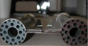
Figure 4. Severely corroded burner compared to a new one. Cross lighter is plugged with rust preventing proper flame propagation.
While some lockouts may be declared to be a “nuisance”, some items also causally related to the IFC must be examined:
- The furnace must have a good ground, all chassis ground connections must be tight. The household ground to the furnace must be connected back to the distribution panel and should not have any voltage on it.
-

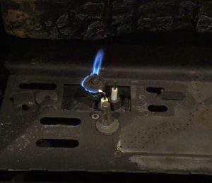
Figure 5. Just this much debris in a cross lighter can prevent flame propogation causing failure to establish a flame signal or even a flashback rough start.
Input voltage to the IFC should be close to the manufacturer’s requirement, typically 120-VAC +/- 10%. Check voltage at the board Line H and Line N input terminals. Polarity must not be reversed.
- Gas pressure: static pressure (should be around 7-in. w.c. before gas valve opens); working pressure (should not drop more than 1-in. w.c. below the static pressure after the gas valve opens); manifold pressure must meet appliance specifications.
Also, the burners must be in alignment, secure and clean. The burner acting as the ground electrode will not conduct the flame signal if it is oxidized or if any of the cross lighters are rusty or plugged with debris (see Figures 4 and 5)
Recycle Lockout?
Because there is such a thing as a nuisance lockout, control board manufacturers (IFC manufacturers) include in the list of potential faults another lockout called “Recycles Exceeded.”
Retries exceeded, as we know, means the IFC tried to light the burner three times but failed. Each time an interpurge was required. However, combustion can be interrupted for other reasons and the control must respond immediately by closing the gas valve.
For example, strong winds blowing across or into the vent terminals could cause a pressure switch (PS) to open for a few seconds, interrupting combustion. Even though the gas valve closes, no interpurge happens as the IFC will have the HSI back on within seconds of the PS re-closing.
Assuming the burners light properly, combustion is restored, and no one is the wiser. This is called a recycle. Some IFC’s may allow this to happen up to 10 times in one call for heat; on the 11th time, the board locks out.
Many IFC’s do not distinguish a re-try lockout from a recycle lockout, the warning LED simply flashes the same number of times forcing the busy technician to do more time-consuming testing.
Newer IFC’s can generate a discrete error code or flash code thus differentiating a retry from a recycle lockout.
In the end, while it is possible the most expensive item in the ignition system is at fault, i.e., the control board, it should not be replaced until all other potential faults have been eliminated as the source of nuisance lockouts. <>
What to do about lockouts
The following images represent some common fault issues, fixes and cautionary tales.
There’s nothing more annoying than a lockout that occurs occasionally, seemingly never while the technician is on site.

In this case, at random, the flame rod was not engaged. When it did light-off on the flame rod, a robust flame signal was generated.
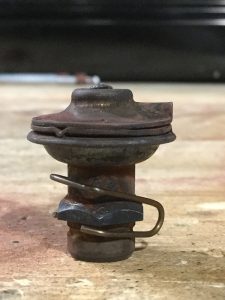
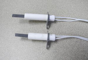
A closer examination on the first visit might have caught the defective pilot burner rather than simply relying on flame signal alone.
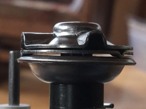
The replacement pilot burner shows proper gapping.
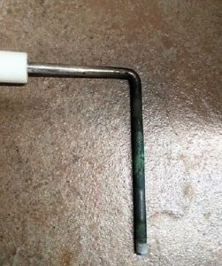
Better to clean or to replace? If the ceramic and metal components are undamaged, cleaning with fine steel wool or non-abrasive plastic pad should work.

Be sure to check the flame signal once the flame rod is re-installed.
Flame rectification circuit: Remember Ohm’s Law? What happens in a circuit if resistance increases and voltage stays the same?
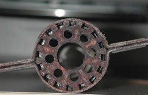
Corroded burners equal increased resistance, which means reduced current, i.e., lower flame signal and potential lockout.
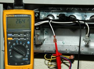
Placing a DC microammeter in series with the flame rod. Typically, one DC microamp is enough for the combustion cycle to continue, however, a much stronger signal is a good insurance policy against lockouts.

Ian McTeer is an HVAC consultant with 35 years of experience in the industry. He was most recently a field rep for Trane Canada DSO. McTeer is a refrigeration mechanic and Class 1 Gas technician.
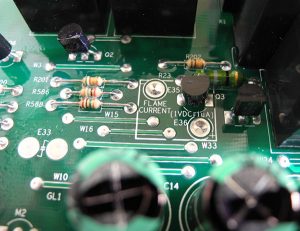
Newer control boards often provide easier access to the flame signal, such as via these solder pads. Simply touch the pads using a DC voltmeter and read-off the flame signal using this formula:
1 DC volt = 1 microamp.
Note: the manufacturer may warn that the DC voltage measured at the pads will vary depending on the VOM used and the voltage supplied to the furnace. In this case, the acceptable range is 0.75 to 3.0 DC microamps.
Hot surface igniter failures can cause lockouts. Formerly some of the furnace makers used White-Rodgers 80-volt ignitors. Since silicon nitride igniters are reasonably robust, the 80-volt system has become obsolete in favour of 120-volt igniters.
When replacing an igniter or a control board on older units, be sure the component voltages are a match. If a replacement control board comes as a kit including a new HSI, be sure to replace the existing igniter.

