
Higher efficiency circulators are here to stay
May 16, 2017 | By John Siegenthaler
Wet-rotor circulators have been used in millions of residential and light commercial hydronic systems over the last four decades. Many hydronic pros consider them “commodity” components. They are available from a long list of suppliers, most of which provide equivalency charts so installers can quickly switch from one make and model to another. The North American market for small wet-rotor circulators is very competitive and highly price sensitive.
Wet rotor circulator technology got to where it is today through continuous design and manufacturing improvements and good value engineering. Along the way there were successes and failures, lessons learned and patents filed.
Consider this: A small wet rotor circulator gets installed in an environment that is hot, wet, pressurized, potentially corrosive and likely littered with some amount of dirt, metal chips, or other debris. That circulator is expected to perform within that environment for at least 20 years with zero maintenance. I have several wet rotor circulators in my own house that were manufactured in the 1970s and have performed flawlessly, with zero maintenance to the present.
What other electrically-powered device with moving parts could match these expectations; dishwashers, refrigerators and washing machines? There is virtually no chance that most currently manufactured appliances will last as long as a wet rotor circulator. The pump manufacturers have done a good job.
Given this record it would seem the old adage: “If it ain’t broken, don’t fix it” should apply. Why would the industry have any interest in replacing or upgrading a product that performs so well? The predominant driver is energy efficiency. Manufacturers strive for efficiency gains from a competitive standpoint, while energy-related government agencies encourage or mandate improvements.
Although relatively inexpensive and reliable, a typical wet-rotor circulator with a permanent split capacitor (PSC) motor is not very good at converting electrical energy into mechanical energy (what the hydronics industry calls “head”) and imparting that energy to the fluid in a system.
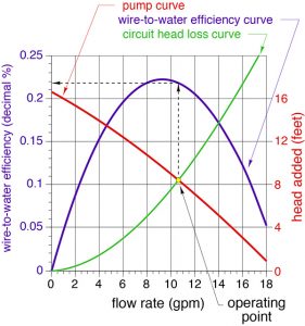
Figure 1
I often ask attendees at training events how efficient they think a typical small wet rotor circulator is at converting electricity into head energy. Guesses usually range from 50 to 80 per cent. After all, as an industry we are used to high boiler efficiencies. Why shouldn’t circulators be expected to deliver comparable results? Some of those attendees are taken aback to learn that the efficiencies of small wet rotor circulators fall far short of their guesses. We will get to the actual numbers shortly.
There are several reasons for relatively low efficiency. A wet rotor circulator needs a larger gap between its rotor and stator coils compared to the gap in an air-cooled motor. This decreases motor efficiency. So does the need to induce a magnetic field in the rotor of a PSC motor relative to other more recently developed motor options. The price at which these products go to market, combined with performance expectations, does not allow for mechanical detailing such as polished volutes, internal turning vanes, tiny clearances between the impeller and volute, or precision ball bearings to support the rotor shaft.
CURVOLOGY
Figure 1 shows several curves that determine and describe the performance of a small wet rotor circulator with (PSC) motor. They include the pump curve, circuit head loss curve and “wire-to-water” efficiency curve.
The red curve is the pump curve. It shows the head energy added to the water by the circulator, as a function of the flow rate through it. The left side of the curve represents conditions where the circulator adds more head energy (foot•pounds of mechanical energy per pound of fluid passing through the circulator), while flow through the circulator is low. The right side shows conditions where the head energy added per pound of fluid is lower, but the volume of fluid passing through the circulator in a given time is higher.
The green curve is a circuit head loss curve. It quantifies the ability of a piping circuit to dissipate head energy from the fluid as it passes through the circuit. This curve is determined based on pipe material and size, as well as the fittings, valves, or other flow-through devices in the circuit, and the characteristics of the fluid.
The flow rate at which the circuit operates is found by drawing a line down from the point where the circulator’s pump curve crosses the head loss curve of the piping circuit. That point is appropriately called the “operating point” for that specific combination of circulator and piping circuit.
The purple curve shows the “wire-to-water” efficiency of the circulator. It quantifies the ability of the circulator to convert electrical energy into head energy and impart that energy to the fluid. The fact that wire-to-water efficiency is a curve rather than just a number indicates its dependence on the flow rate through the circulator. The wire-to-water efficiency ranges from zero, if the circulator is operating but no flow is passing through it due to a blockage in the circuit, up to some maximum value. For the circulator represented in Figure 1, the maximum wire-to-water efficiency is about 22.4 per cent.
In an ideal application, the circulator’s operating point falls directly under the peak of the wire-to-water efficiency curve. However, designing systems that operate at this “sweet spot” is the exception rather than the rule. Still, it is an ideal to be aware of and strive for when refining system design.
A guideline I suggest is to select a circulator so that the operating point falls within the middle third of the pump curve. In Figure 1 the operating point falls just to the right of the peak of the efficiency curve. This system would operate with a wire-to-water efficiency of about 21.9 per cent, compared to the maximum possible wire-to-water efficiency of about 22.4 per cent. That is a very acceptable difference.
MOTOROLOGY
Over the last decade, many of the fans and blowers used in residential and light commercial HVAC equipment have transitioned from permanent split capacitor (PSC) motors to brushless DC motors. The latter are often called ECMs, which stands for electronically commutated motor. Brushless DC motors use powerful and permanent rare earth magnets within their rotors. The magnetic field produced by rare earth permanent magnets are also very strong, resulting in motors that offer higher torque and more power, while being significantly smaller than PSC equivalents.
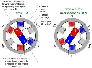
Figure 2
In modern high efficiency circulators, the permanent magnet is sealed inside a stainless steel “can” that is fastened to the shaft and impeller assembly. That assembly rotates to follow the moving magnetic fields created by the wire-wound stator poles that surround the rotor as shown in Figure 2.
The magnetic polarity of a stator pole can be rapidly switched by alternating the direction of electrical current through the pole’s winding. This switching is regulated by a microprocessor within the circulator. The frequency at which the polarity is switched, and the precise timing of these changes, allows the circulator’s impeller to spin over a wide range of speed. That speed can be controlled by anything that properly communicates with the microprocessor. This includes predefined control modes that are factory-programmed into the circulator’s non-volatile memory, as well as signals from external controllers. The latter includes analog inputs such as a variable 0-10 volt DC signal, or digital inputs supplied as a predefined pulse width modulation (PWM) signal. Larger high efficiency circulators can also be configured to accept signals from building automation protocols such as BACnet or LonWorks.
CONSTANT VERSUS PROPORTIONAL ∆P
Two common operating modes that are factory-programmed into the non-volatile memory of high efficiency circulators are:
Constant differential pressure mode (abbreviated as ∆Pc)
Proportional differential pressure mode (abbreviated as ∆Pv)
These operating modes allow the circulator to be configured based on the piping system it will be used in. Both operating modes are intended for use in multi-branch systems where each branch contains a valve to regulate flow. These valves might be simple zone valves that are either fully open or fully closed at any given time. They could also be modulating valves. Two examples of the latter are thermostatic radiator valves and motorized two-way globe valves.
Both ∆P operating modes adjust differential pressure so that the flow rate in a given branch remains as stable as possible while flow in other branches changes. For example, if the design flow rate through zone one of a four-zone distribution was two gpm when all other zones are open, it should remain close to two gpm regardless of what is happening with flow in the other zones.
The ∆Pc operating mode is best applied in systems where the head loss of the branch circuits is much greater than the head loss of the common piping. The latter is the piping through which all system flow passes. It includes the headers serving the branch circuits and usually some additional piping carrying flow through a heat source, hydraulic separator, or heat exchanger.
Designers should always keep the head loss of the common piping as low as practical. Keep headers short and generously sized. I suggest a maximum flow velocity of two feet per second through headers assuming all branches are on. If the heat source has high head loss characteristics such as a compact heat exchanger in a mod/con boiler, or a coiled coaxial heat exchangers in a heat pump, isolate that head loss from the common piping using a hydraulic separator, closely spaced tees, or a buffer tank.
One of the best examples of systems where ∆Pc is well applied is a homerun distribution system, as shown in Figure 3.
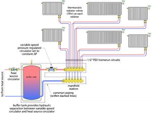
Figure 3
The common piping in Figure 3 is outlined by dashed lines. It consists of short headers, generously sized piping and a buffer tank that provides hydraulic separation between the heat source circulator and the variable speed distribution circulator.
Think of ∆Pc mode as “cruise control” for differential pressure. The installer sets the ∆P required at design load, when all branches are operating at full flow for example. The circulator then monitors the current ∆P and compares it to the set ∆P. This monitoring is “sensorless.” Flow rate and differential pressure are inferred based on the electrical operating conditions of the circulator in comparison to “mapped” electrical performance data stored in the circulator’s memory.
If the ∆P across the circulator decreases, the motor speed increases to reestablish the set ∆P and vice versa. Because the head loss of the common piping is very low in comparison to the head loss of the branch circuits, the ∆P across the circulator is almost the same as the ∆P across the manifold station. Maintaining a constant ∆P across the manifold station keeps the flow rate in each branch circuit stable, regardless of the flow in other branches.
When the speed of a circulator changes so does its pump curve. Reducing speed shifts the pump curve to the left and downward. Increasing speed shifts the pump curve to the right and upward.
The head loss curve of the distribution system also changes as the valves in branches open, close or modulate flow. When valves open the head loss curve becomes shallower and when valves close it becomes steeper.
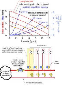
Figure 4
Figure 4 shows how a variable speed circulator operating in ∆Pc mode changes its pump curve in combination with the shifting head loss curves, so that the operating point tracks along a horizontal path and thus maintains a constant differential pressure across the circulator.
The ∆Pv mode is best applied in systems where the head loss of the “mains” piping is significant relative to the head loss through the branches. Two specific and common piping layouts fit this description: two-pipe direct return distribution systems and two-pipe reverse return distribution systems. Figure 5 shows an example of the latter.
When operating in ∆Pv mode, the head produced by a circulator decreases linearly with decreasing flow rate, as shown in Figure 6.
The head added by the circulator a zero flow rate is typically constrained at 50 per cent of the head setpoint for design load (e.g., the head required when all branches are at full flow). This relationship between head and flow, combined with the characteristics of a two-pipe distribution system, create conditions that maintain relatively stable flow through each branch regardless of flow in other branches.
Both ∆Pc and ∆Pv operating modes eliminate the need for a differential pressure bypass valve in the system. The latter was a common means of limiting variations in differential pressure when fixed speed circulators were used in systems with valve-based zoning. And, unlike a differential pressure bypass valve, which regulates pressure by dissipating excess head energy, both ∆Pc and ∆Pv operating modes reduce electrical power demand by the circulator whenever flow or head decreases. Estimated operating cost savings vary by manufacturer, model and operating mode, but claimed savings range from 60 per cent to as much as 90 per cent compared to fixed speed circulators with comparable hydraulic characteristics and AC induction motors.
ADDITIONAL CAPABILITIES
Some high efficiency circulators have built in firmware routines that pulse the impeller at start up to dislodge any entrapped air. Some also have built in temperature and flow sensors. When combined with another temperature sensor on the opposite side of the circuit, some high efficiency circulators can be set to maintain a fixed temperature difference between the supply and return sides of the circuit. Some can even calculate and report the rate of heat transport in the circuit based on an internal flow sensor combined with two temperature sensors.
WHAT’S AHEAD
In Europe, the use of standard circulators with PSC motors in stand-alone applications (e.g., those not integrated into a product) ended in January 2013. Only circulators meeting energy use limits established through simulated usage profile testing can be legally installed in European Union countries. Standard wet rotor circulators with PSC motors, which are still extensively used in North America, fall far short of these limits. By 2020 European energy use standards will also apply to all new and replacement circulators that are integrated into products such as hydronic mixing modules, or pumping stations.
The United States Department of Energy (DOE) is currently working with industry stakeholders to develop energy efficiency standards for smaller hydronic circulators. Although still a work in progress, the eventual standards are likely to set target energy use thresholds not achievable by circulators with PSC motors.
Brushless DC motors with microprocessor-managed speed regulation are all but certain to become the standard for hydronic circulators worldwide. Future circulators using this technology will likely offer increased functionality through more intrinsic operating modes, expanded communication abilities including internet connectivity and artificial intelligence-based adaptation to changing load conditions.
As has been the case with other devices using digital electronics, the price of high efficiency circulators has dropped over the last few years due to market competition and product development trends by global circulator manufacturers. Small higher efficiency circulators that cost upwards of US$400 when first introduced to North America a decade ago, are now available at less than half that price. Some high efficiency circulators with basic functionality have recently dipped below the US$100 retail price point in North America.
I consider the transition from standard wet rotor circulators to high efficiency brushless DC powered circulators one of the biggest advances in hydronics technology over the last 20 years. The eventual replacement of lower efficiency circulators with current and future versions of high efficiency circulators will save multiple billions of kilowatt hours of electricity worldwide.
When it comes to moving water through hydronic systems, high efficiency circulators with brushless DC motors are the new norm.
 John Siegenthaler, P.E., is a mechanical engineering graduate of Rensselaer Polytechnic Institute and a licensed professional engineer. He has over 34 years experience in designing modern hydronic heating systems. Siegenthaler’s latest book, Heating with Renewable Energy, was released recently (see www.hydronicpros.com for more information).
SEE JOHN AT MODERN HYDRONICS-SUMMIT 2017 WHERE
HE WILL BE PRESENTING A KEYNOTE SESSION AND A SESSION
WITH ROBERT BEAN
www.modernhydronicssummit.com

