
A Complete Solution
August 30, 2023 | By John Siegenthaler
John Siegenthaler asks hydronics pros: Are you prepared to deliver a complete package of heating, cooling, DHW and optimized ventilation to your customers?
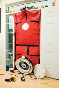
Blower door testing.
Building codes and energy conservation standards continue to evolve, and today many are requiring proof of high-quality air sealing for buildings, with measurements being done through blower door testing.
Typically, the building envelope is depressurized using a flexible panel with a variable speed fan that’s temporarily installed in the opening of an exterior door. By measuring the speed of this fan and correlating it to the slight (but measurable) difference in air pressure between the inside and outside of the building, it’s possible to determine the air changes per hour air leakage rate.
A leaky house could test out at 15 to 20 air changes per hour at 50 Pascals (about 0.00725 psi) of air pressure differential. A well-sealed new house could have air leakage in the range of 1 to 4 air changes per hour at 50 Pascals pressure difference (ACH/50).
And a super-tight house, built to current Passive House standards, must not exceed an air leakage rate of 0.7 ACH/50.
Experience has shown that the “natural” air infiltration rates of buildings will be approximately 1/20th of those established by blower door testing at 50 Pascals differential pressure. Thus, a house with 4 ACH/50 blower door test rating will have a natural air leakage in the range of 0.2 air changes per hour.
You won’t suffocate in such a house, but you’re unlikely to find the air quality provided by air leakage acceptable. Fry up some bacon on Monday, and you’ll still smell it on Wednesday. I could cite more examples of this air quality problem, based on other “facilities” in the house, but I’m confident you get the idea.
Grab It While You Can
The contemporary approach to providing fresh air while at the same time not adding substantially to the home’s heating load, is to install a heat recovery ventilator (HRV), or in some cases an energy recovery ventilator (ERV). Both devices create two air flows: one brings outside air into the building, and the other exhausts “stale” inside air back outside. Both air streams are generated by small blowers within the ventilator.
During the heating season, the stream of incoming cool (or cold) outside air absorbs heat from the warmer exhaust air stream. This exchange takes place within the heat exchange “core” of the ventilator, through which both air streams simultaneously pass, but never mix.
Typical heat recovery efficiency is in the range of 70%. Thus, the fresh air requirement is met using about 70% less thermal energy than would otherwise be needed if the air was simply blown into and out of the building with ventilation fans and no heat exchange.
During the cooling season, the outgoing stream of cool (but “stale”) inside air absorbs some heat from the incoming warm (but fresh) outside air. Again, the fresh air requirement of the building is met, but the energy penalty associated with fully cooling and dehumidifying the incoming air to desired indoor temperature and humidity is greatly reduced.
Energy recovery ventilators (ERVs) provide similar functions to heat recovery ventilators (HRVs). The difference is that ERVs can also exchange moisture (in vapour form) between the ingoing and outgoing air streams.
In winter, some of the moisture in the outgoing (higher absolute humidity) air stream is transferred to the incoming (low absolute humidity) air stream. And in summer, some of the moisture in the incoming (higher absolute humidity) air stream is transferred to the (lower absolute humidity) outgoing stream.
This moisture exchange helps maintain a comfortable (and healthy) indoor relative humidity in winter and it also reduces the latent cooling load in summer.
Add On
So, what does this have to do with hydronics?
Well, in combination with an air-to-water heat pump, or a geothermal water-to-water heat pump, heat recovery ventilation becomes another part of the “total solution” package you can offer. That package includes heating, cooling, domestic hot water and ventilation.
For example, consider a relatively simple system that provides multiple zones of space heating using panel radiators, and “whole house” cooling using a ducted chilled water air handler.
It also provides domestic water heating using energy from both the heat pump and an electric resistance backup heater. Figure 1 shows one concept for such a system.
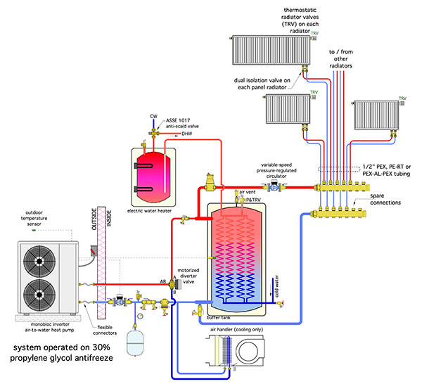
The heat pump maintains the buffer tank between some upper and lower temperature limits. Those limits could be set points or determined using outdoor reset control. Some air-to-water heat pumps have integrated controls that allow either.
The variable-speed pressure-regulated circulator operates continuously during the heating season. Warm water passes through any panel radiator with a partially-open or fully open thermostatic radiator valve. A system that is simple, elegant and even “wireless.”
The motorized diverter valve routes heated fluid from the heat pump to the buffer tank. This flow path is only open when the heat pump is operating.
The path between ports AB and A close as soon as the heat pump turns off, preventing reverse thermosiphoning from the tank.
This valve operation also prevents flow returning from the distribution system from passing through the heat pump when it’s off.
The large coils inside the buffer tank preheat domestic water. The temperature rise of the water depends on the fluid temperature maintained in the tank’s shell, the surface areas of the internal coils, and the rate at which domestic water flows through the coils.
If the tank shell temperature is maintained close to the desired domestic hot water delivery temperature it’s possible that over 90% of the total temperature rise can occur through the coils.
The remaining temperature rise is handled by a tank-type electric water heater, or a tankless electric water heater
If the buffer tank temperature is based on outdoor reset control, the auxiliary water heater will need to contribute more energy for domestic hot water during milder outdoor temperatures.
In either case, the electric water heater provides a backup source of domestic hot water if the heat pump were down for service.
Chilled to Perfection
Cooling is provided by routing chilled water from the heat pump, through the diverter valve, to the coil of an air handler.
The variable speed compressor in the heat pump automatically adjusts to maintain a set chilled water delivery temperature — typically in the range of 45 to 55F (7 to 12C).
The chilled water flows through the coil of an air handler equipped with a condensate drip pan. Cooled and dehumidified air is delivered to the entire building through a ducting system.
The original system shown in Figure 1 cannot simultaneously heat the buffer tank and send chilled fluid to the air handler. One of these loads must take priority over the other.
If maintaining the temperature of the buffer tank is the priority, so as to maximize preheating of domestic water, the system controls would be configured to temporarily stop chilled fluid production and flow to the air handler coil while the temperature of the buffer tank is boosted, which typically only takes 5 to 10 minutes.
If cooling is the priority, heat input to the buffer tank needs to be temporarily interrupted when the house thermostat calls for cooling. If the cooling call is sustained, the electric water heater can take over the DHW load until the cooling load is satisfied.
Dual Purpose Ducting
Since there’s going to be a ducting system for cooling, why not use it for ventilation?
Doing so would certainly reduce cost compared to installing another air distribution system solely for ventilation.
In fact, why not enhance the system by using the coil in the air handler for “boosting” the temperature of incoming ventilation air during cold winter operation, and thus eliminate possible cool air delivery to the house?
Figure 2 (below) shows one approach for connecting the HRV (or ERV) to the return trunk duct of the air handler, along with hydronic trim to provide that boost function.
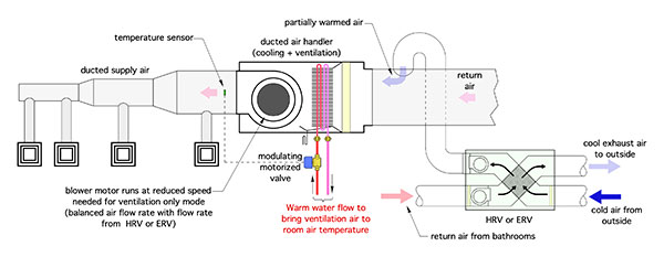
Figure 2.
The smaller ducts on the “house side” of the HRV connect to the return trunk leading into the air handler. The “stale” air is pulled from one or more bathrooms. The fresh outdoor air, after absorbing heat from the exhaust stream, is injected into the return air side of the air handler.
This configuration can operate in three different modes:
- Ventilation-only mode
- Cooling plus ventilation mode
- Ventilation plus boost mode
For ventilation-only mode the blower in the air handler should provide an air flow rate just above that of the HRV. This ensures that all the incoming fresh air will be entrained in the air flow that’s headed for the diffusers in the house. It also reduces input power to the blower motor in the air handler.
Most air handlers have blower motors with multiple speed tap wiring. Check with the air handler manufacturer regarding the best option to bring the air flow rate down to perhaps 100 to 150 cubic feet per minute (CFM). Some air handlers may not be able to reduce their blower speed to such a low value. That’s okay from the standpoint of distributing fresh air. It just means higher electrical power consumption by the blower.
During cooling mode the blower speed would be set to provide 350 to 400 CFM of air flow per ton of cooling capacity. Thus, for an air handler delivering 3 tons (36,000 Btu/h) of cooling, the air flow rate would be about 1050 to 1200 CFM. Again, this will require the system to use the appropriate speed tap on the blower motor.
The ventilation plus boost mode is intended for times when outdoor temperatures are cold. The intent is not to heat the house with the ventilation air, it’s to introduce air into living spaces at about the same temperature as those spaces.
For example, assume the outside temperature is -10F (-23C), and the HRV is recovering about 70% of the heat from the exhaust air stream that leaves the occupied space at 70F (21C).
This would make the fresh air temperature delivered from the HRV about 46F (8C). That’s going to feel pretty cool to occupants if it’s not carefully mixed with room air before reaching occupied areas.
If the boost function is used, this air could be introduced in occupied spaces at a neutral temperature and far less concern about creating uncomfortable conditions when it’s frigid outside.
Under these conditions it’s possible to pass heated fluid through the air handler’s coil to boost the temperature of the ventilation air prior to introducing it to occupied space. A modulating two-way valve is used to regulate the flow of warm fluid through the coil. The flow rate is controlled based on maintaining a set supply air temperature on the outlet side of the air handler.
A word of caution is in order. If the system is located where outdoor temperatures are well below freezing much of the winter, the coil in the air handler needs to be protected against freezing. That’s “automatic” with the monobloc air-to-water heat pump system shown in Figure 1 because the entire system operates with a 30% solution of propylene glycol.
If the system operated with water only, some type of failsafe control would be needed to automatically turn off the HRV if the coil in the air handler approaches a potential freezing condition.
Figure 3 (below) shows the same system as Figure 1, but with the piping needed to supply water to the air handler coil.
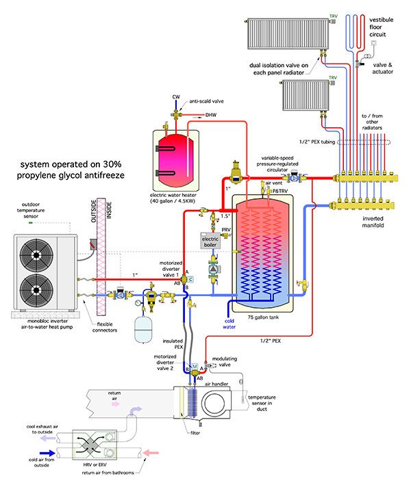
Figure 3.
The coil is supplied through a three-way diverting valve. When this valve is off, the coil is connected to the piping path for cooling. When the valve is energized the coil is connected to the warm water circuit.
The pressure differential to drive the latter is supplied by the continuously operating distribution circulator. The modulating two-way valve regulates the flow rate through the coil based on maintaining a set air delivery temperature.
This valve should be selected with an equal percentage characteristic.
Offer it all
The longstanding “stigma” that residential hydronic systems can’t provide cooling is slowly waning as air-to-water and geothermal water-to-water heat pumps gain market share against boilers. This sets the stage for progressive hydronic professionals to offer heating, domestic hot water, and cooling.
Why not extend this even farther to include heat recovery ventilation (HRV)? The market for such total solutions is quickly developing.
Are you prepared to participate and profit? <>
 John Siegenthaler, P.E., has over 40 years of experience designing modern hydronic heating systems and is the author of Modern Hydronic Heating (4th edition) and Heating with Renewable Energy (visit hydronicpros.com).
