
A look at air-to-water heat pump systems
May 31, 2018 | By John Siegenthaler
Heat pumps are destined to carve out an increasing percentage of future residential and light commercial HVAC market. This trend is based on the convergence of market drivers such as increasing electrical generation by utility scale photovoltaics and wind turbines, government renewable energy targets, growing interest in net zero buildings, and implementation of programs to reduce carbon emissions produced by burning fossil fuels.
Heat pumps can be applied in many situations where low temperature heat is freely available and a load is present to accept that heat at a higher temperature. Heat pumps are used for space heating, domestic water heating, heat recovery ventilation, and even recovering useful heat from sewer effluent.
Most heat pumps used for space heating also have the ability to provide cooling and dehumidification. Thus, selecting a heat pump for space heating often displaces the need for a separate cooling system, as would be required for hydronic systems using boilers.
EVERYONE LOVES GEO
Geothermal heat pumps that extract heat from ground water, or buried earth loops, have become the “darling” of the North American HVAC market. Government incentive programs, in both Canada and the U.S., now offer generous rebates or tax credits that significantly lower the installed cost of geothermal heat pump systems.
The predominant “pitch” for using geothermal heat pumps is the ability to operate at higher coefficients of performance (COPs) relative to air source heat pumps in cold climate applications. This advantage became the focus of utility incentive programs during the 1980s. The utilities viewed geothermal heat pumps as a means of “quality load growth.” The ability to increase electrical energy sales while reducing the peak demands associated with electric resistance heat to back up early generation air source heat pumps during cold weather.
While the COP advantage of geothermal heat pumps generally remains true, the “COP gap” has been steadily closing due to refinements in “cold climate” air-source heat pump technology.
The difference in annual space heating cost between a heat pump with a seasonal average COP of 3.5 versus a different heat pump with a season average COP of say 2.5 shrinks in direct proportion to the building’s design heating load.
I recently ran an analysis of two heat pumps: A geothermal heat pump with an assumed seasonal average COP of 4.0, and a cold climate air-to-water heat pump with a seasonal average COP of 2.5. Both heat pumps were assumed to supply heat to an energy efficient house in a cold upstate NY climate of 6720 heat degree days. The design heating load of the house was 18,000 Btu/hr.
The electrical energy saved by the higher COP heat pump over the other heat pump was about 3.7 MMBtu/h (1 MMBtu = 1,000,000 Btu). With electricity priced at $0.13/kwhr, the annual savings in heating energy was about $142. That is far less than what most people spend for a year of cell phone service.
The geothermal heat pump with the higher COP does reduce space heating cost. However, the question that remains is: Can the significantly higher installation cost of the geothermal heat pump be amortized by the savings it produces over the life of the equipment? Without the subsidies now available for geothermal heat pumps, and when competing against unsubsidized low-ambient air-source heat pumps, the economic viability of the higher performance/high price system remains dubious. Using local costs in upstate NY I find the simple payback of the higher cost system well beyond an estimated 25 year life cycle.
HEAT PUMPS + HYDRONICS
I am a firm believer that no heating technology, no matter how energy efficient, will gain and retain market share if it fails to deliver excellent comfort.
Heat pumps that deliver heat using forced air distribution systems are saddled with many of the comfort compromises as other forced air distribution systems. These include potential for temperature stratification, drafts, building pressurization that increases air leakage, the sound of forced air delivery, and dust accumulation within ducting. Good HVAC hygiene such as duct cleaning, use of HEPA filters or electronic air cleaners can reduce dust issues, but the physiological comfort mismatch between a forced air delivery systems versus properly designed radiant panel systems remains.
So, how do you put together the combination of:
- High energy efficiency in cold climate applications
- Renewably-sourced electricity
- Superior comfort
- Unsubsidized economic sustainability?
One solution where these desirable traits converge is a low-ambient air-to-water heat pump combined with a low temperature radiant panel distribution system.
Current generation low-ambient air-to-water heat pumps can extract useable heat from outdoor air at temperatures down to -8F, (-22C). That heat can be transferred to a steam of water or antifreeze solution, and supplied to a hydronic radiant panel distribution system at temperatures up to 130F (54C).
During warm weather the same heat pump can produce chilled water or antifreeze solution down to temperatures of 42F (5.5C). That fluid can be passed through the cooling coils of one or more air handlers to cool and dehumidify interior space.
BASIC SYSTEM CONFIGURATION
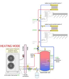
Figure 1
Figure 1 shows a piping schematic for an air-to-water heat pump system that provides zoned heating using radiant panels, and zoned cooling/dehumidification using small air handlers.
Both zones must operate in the same mode (e.g., heating or cooling) at the same time. Flow to all heating and cooling zones is provided by a single variable-speed pressure-regulated circulator that automatically changes speed to maintain constant differential pressure regardless of which zone(s) are operating.
During heating operation, the fluid temperature in the buffer tank is determined by an outdoor reset controller. The maximum target water temperature at the mid-height sensor (S1) in the buffer tank is 110F, corresponding to an outdoor temperature of 0F. The minimum target water temperature at sensor (S1) is 80F, corresponding to an outdoor temperature of 52.5F or higher. Outdoor reset control of the buffer tank temperature allows the system to meet the heating load of the building while maintaining the lowest possible water temperature required of the heat pump. This maximizes its coefficient of performance.
The buffer tank is shown in a “three-pipe” configuration. This allows heated or chilled fluid from the heat pump to go directly to the load without first passing through the buffer tank. At the same time it couples the thermal mass of the lower portion of the tank to the heat pump to prevent short cycling. This piping also allows the buffer tank to provide hydraulic separation between the heat pump circulator (P1) and the load circulator (P2). The piping is optimized to preserve stratification during heating mode operation.
The entire system is filled with a 30 per cent solution of inhibited propylene glycol antifreeze.
CHILLING OUT
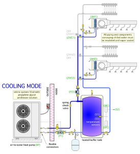
Figure 2
Figure 2 shows the system in cooling mode. Chilled antifreeze solution from the heat pump or buffer tank is delivered to one or both of the zoned air handlers, while the radiant panel zones remain off. During cooling operation the temperature of the buffer tank is maintained between and upper and lower limit by a setpoint controller. A typical temperature range would be between 45F and 60F.
All piping carrying chilled fluid must be insulated and vapor sealed to prevent condensation. Migration of chilled water into the radiant panel zones is prevented by a combination of a closed zone valve on the supply pipe and a check valve on the return side piping.
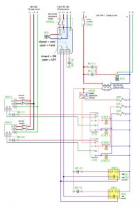
Figure 3
Figure 3 shows one way to wire electrical controls for the system.
The mode selection switch determines if the system operates in heating, cooling, or remains off. The temperature in each zone is monitored by a heating/cooling thermostat. In cooling mode the zone thermostats turn on their respective air handlers, and open their associated zone valves. The distribution circulator is also turned on. A demand for cooling from either zone also turns on a setpoint controller that operates the heat pump to maintain the buffer tank temperature within a suitable temperature range for cooling.
DESCRIPTION OF OPERATION
The following is a description of operation for the system shown in Figures 1, 2, and 3. Specific makes and models of heat pumps may require slightly different wiring to enable operation in heating or cooling modes. Always verify the specific wiring requirements for the heat pump being used, and ensure it is coordinated with the balance of system wiring.
Power supply: The air-to-water heat pump and circulator (P1) are powered by a dedicated 240/120Vac 30 amp circuit. The heat pump disconnect switch (HPDS) must be closed to provide power to the heat pump. The remainder of the control system is powered by 120Vac/15 amp circuit. The main switch (MS) must be closed to provide power to the control system. Both fan-coils are powered by a dedicated 240Vac/15 amp circuit. The service switch for each air handler must be closed for that air handler to operate.
Heating mode: The mode selection switch (MSS) must be set for heating. This passes 24Vac to the RH terminal in each thermostat. Whenever either thermostat (T1, T2) demands heat, 24Vac is passed from the thermostat’s W terminal to the associated heating zone valve (ZVH1 or ZVH2). When the zone valve reaches its fully open position, its internal end switch closes, passing 24Vac to relay coil (R1). Relay contact (R1-1) closes to pass 120Vac to circulator (P2). Relay contact (R1-2) closes to pass 24Vac to the outdoor reset controller (ODR). The (ODR) measures outdoor temperature at sensor (S2), and uses this temperature, along with its settings, to calculate the target supply water temperature for the buffer tank. It then measures the temperature of the buffer tank at sensor (S1). If the temperature at (S1) is more than 6F below the target temperature, the (ODR) closes its relay contact. This completes a circuit between terminals 1 and 2 in the heat pump, enabling it in heating mode. The heat pump (HP) turns on circulator (P1) and verifies adequate flow through the heat pump. After a short time delay, the heat pump turns on it compressor. The heat pump continues to operate until the temperature at sensor (S1) is 6F above the target temperature calculated by the (ODR), or neither thermostat calls for heat, or the heat pump reaches its internal high-limit setting. Note: Neither air handler operates in heating mode, regardless of the fan switch setting on the thermostats.
Cooling mode: The mode selection switch (MSS) must be set for cooling. This passes 24Vac to relay coil (RC). Normally open contacts (RC-1) and (RC-2) close, allowing 24Vac from the air handlers to pass to the RC terminal in each thermostat (T1, T2). Whenever either thermostat calls for cooling, 24Vac is passed from the thermostat’s Y terminal to the associated cooling zone valve (ZVC1 or ZVC2). When the zone valve reaches its fully open position, its internal end switch closes, passing 24Vac to relay coil (R2). Relay contact (R2-1) closes to pass 120Vac to circulator (P2). Relay contact (R2-2) closes to pass 24Vac to the cooling setpoint controller (SPC). The cooling setpoint controller measures the temperature of the buffer tank at sensor (S3). If this temperature is 60F or higher, the (SPC) relay contact closes, completing a circuit between terminals 1 and 2 on the heat pump (HP) enabling it to operate. Relay contact (R2-3) closes between terminals 3 and 4 in the heat pump (HP), switching it to cooling mode. The heat pump (HP) turns on circulator (P1) and verifies adequate flow through the heat pump. The heat pump compressor turns on it compressor and operates in chiller mode. This continues until the temperature at sensor (S3) drops to 45F, or until neither zone thermostat calls for cooling, or until the heat pump reaches in internal low-limit setting. The blowers in the air handlers can be manually turned on at the thermostats when the mode selection switch (MSS) is set to cooling. The blowers will operate automatically whenever either cooling zone is active.
Distribution: Circulator (P2) is a variable speed pressure-regulated circulator that is set for the required differential pressure when both heating zones, or both cooling zones, are operating. It will automatically reduce speed to maintain a constant differential pressure when only one heating zone, or one cooling zone is operating. Automatic flow balancing valves with present flow rates, are installed on both heating zone circuits and both cooling zone circuits.
Low-ambient air-to-water heat pumps can fill a unique niche for heating and cooling of residential and light commercial buildings. Although their COPs are not necessarily as high as geothermal heat pumps, their installation cost is substantially less. They’re especially well suited as heating sources for low temperature radiant panel distribution systems. I recommend that you take a good look at how they might fit into your business model. <>
John Siegenthaler, P.E., is a mechanical engineering graduate of Rensselaer Polytechnic Institute and a licensed professional engineer. He has over 34 years experience in designing modern hydronic heating systems. Siegenthaler’s latest book is Heating with Renewable Energy (see www.hydronicpros.com for more information).

