
Compressors through the years
March 24, 2020 | By Dave Demma
An overview of how compressor technology has been making strides in both operational and energy efficiency.
I grew up in Northern California and was of high school age during the late 1960’s. While there were many things unique to that time period, the creative explosion in popular music was unparalleled: The Beatles, Cream, Jimi Hendrix, The Stones, Deep Purple, Jefferson Airplane, Joni Mitchell, The Doors, The Kinks, King Crimson, Neil Young, … I could go on.
All of these acts would have made stops in the San Francisco area, performing at one of the many concert venues, including the Winterland Arena. You might be thinking, “Curious name for a concert venue.” Indeed, a very curious name.
Originally opening in 1928 as The New Dreamland Auditorium, in the late 1930s the building was upgraded with a “modern” refrigeration system providing the cooling capacity for a newly installed ice-skating rink.
In 1966, legendary rock promoter Bill Graham began using Winterland Arena as a concert venue, and the rest is history.
But what does this have to do with compressors? While working as a refrigeration technician in the San Francisco area in the mid-1970s, the company I was employed by received a call from the caretaker at Winterland Arena. He was concerned by the presence of the very distinct odour of ammonia in the building.
Having attended several concerts at Winterland, I was excited about seeing a different side of the venue, including what could be considered as museum-worthy refrigeration equipment. I gladly took the service call. As this was long before the advent of digital cameras, I took the opportunity to swing by my house and pick up my camera, wanting to capture the day’s events on film. The caretaker greeted me and offered a tour of the old building, showing me the dressing rooms, reception areas, the backstage area, and all the while sharing anecdotes from various concerts and music groups. He even gave me a guitar pick that belonged to Stephen Stills. From the upper balcony, which overlooked the stage below, you could almost hear the ghosts of concerts past in the complete dead silence of the empty arena. After the tour we finally made our way to the fully intact ammonia chiller from the 1930s.
Above is a photo of the compressor room, showing twin Carbondale two-cylinder compressors, driven by open frame synchronous motors. These compressors were large bore/large stroke, depending on the capacity, anywhere from 6-in. x 6-in. to 10-in. x 10-in. Given the huge piston mass and large stroke, these machines typically operated between 300 to 400 RPM. Barring any serious system-related issues, the low compressor RPM allowed these beasts to operate relatively trouble-free for years.
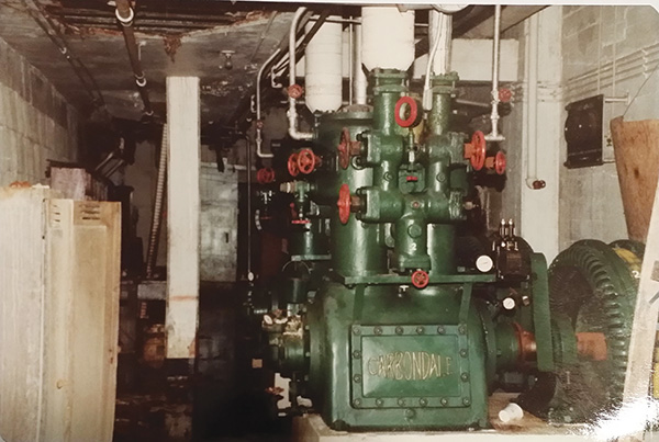
Twin Carbondale two-cylinder compressors in the old Winterland Arena.
Those compressors, while not brand new, still struck me as an example of machinery as art. But the item that really caught my eye was the gauge panel (pictured above). Given that the system was no longer in use, I did my best to persuade the caretaker to let me remove the gauge panel, as it would have made a stellar addition to my collection of equipment artifacts. But alas, he wouldn’t agree to that. It is an absolute thing of beauty, representative of craftsmanship from a bygone era.
So, what is the point of this stroll down memory lane? It gives some perspective to the advances that have been made in compressor design, and particularly compressor efficiency. Somewhere I have a copy of an ad from the York Ice Machinery Company (as they used to be known), showing the contrast in size between a 6 x 6 compressor and their “new” semihermetic reciprocating compressor. Not only was the motor fitted inside the compressor body, but the small diameter pistons and reduced piston stroke allowed the compressor to operate at a much higher RPM. This allowed this relatively “small” compressor to have the same Btu capacity as the gargantuan 6 x 6. This design also eliminated the need for a compressor shaft seal, which was a potential leak path. It also eliminated the need for drive belts, motor to compressor alignment and periodic motor bearing lubrication.
That was just a first of many in the evolution of compressors. Below are a few more.
Discus Valve Plate
Piston compressors, by their nature, have a built-in inefficiency. Since volume is proportional to pressure, as the piston travels upwards during the compression stroke, the resulting reduction in cylinder volume causes the vapour pressure to increase. The cylinder volume would have to be reduced to zero for all of the compressed vapour to exit the cylinder. This is not possible, as there is some volume resulting from the clearance between the top of the piston and the bottom of the valve plate, along with the volume resulting from the discharge port in the valve plate, which means that some vapour remains at top dead centre of the compression stroke. This volume is known as “clearance volume.” Before suction vapour can enter the cylinder during the intake stroke, some portion of piston travel is necessary to re-expand the clearance volume vapour.
And, that portion of piston travel dedicated to re-expanding the clearance volume vapour provides absolutely no tangible work. So, the as the discharge pressure increases in relation to the suction pressure (compression ratio), or as the clearance volume increases, the compressor capacity reduces. Figure 1 shows comparative photos of a reed valve plate and a discus valve plate. The discus valve plate eliminates the discharge port in the valve plate, as the discus discharge valve is completely flush with the underside of the valve plate, thus eliminating a portion of the clearance volume vapour that has to be re-expanded during the intake stroke.
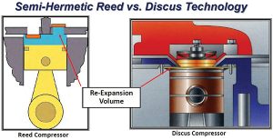
Figure 1. Comparison of a reed valve plate and a discus valve plate in piston compressors.
Scroll Compressors
Production of scroll compressors started in 1988. While they operate on the same basic principle as a piston compressor—in that there is a proportional relationship between pressure and volume, and reducing the vapour volume results in an increase in pressure—the scroll has one distinct advantage, the action produced by the rotating scroll plate moving against the fixed scroll plate results in the volume where suction vapour enters the scroll set being reduced to zero prior to the compressed vapour exiting the centre discharge port.
Hence, there is no re-expansion of high-pressure vapour (figure 2). The compression cycle is 100% efficient. Compressors are selected based on design conditions for a particular application. Those conditions constitute the worst case scenario where the greatest amount of capacity is required. For refrigeration applications, these include periods after defrost cycles, warm product being loaded into a refrigerated space and high ambient temperatures in summer. When the actual load conditions are less than the design condition, the compressor capacity would be greater than required. As such, without some means of operating at a reduced capacity, the compressor not only provides capacity greater than required, but the electrical consumption is in excess of what is necessary. Technology improvements have been made to address the standard compressor’s inability to match capacity with the load.
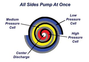
Figure 2. Scroll compressors, a more efficient compression cycle.
Copeland Digital Scroll
The Digital Scroll differs in design from the standard scroll in that it has the ability to allow the top scroll plate to “lift” approximately 1-mm from its normal position. This is enough to completely eliminate the scroll plate’s ability to compress vapour. The result is 100% unloading capability.
This is where the “digital” part comes in. Through the abilities of electronic controllers, the compressor can now operate in segments of “cycle time,” which is comprised of the sum of “loaded state cycle time” and “unloaded state cycle time.”
Plainly speaking, the compressor operation can be broken down into cycles of 20 seconds, with some portion of the 20 seconds operating completely loaded, and some operating completely unloaded. The capacity of the digital scroll can vary between 10% and 100%. The compressor capacity can be calculated from a ratio of percentage of loaded state time to the total cycle time. For example, if the loaded state time were 10 seconds, and the total cycle time were 20 seconds, the compressor capacity would be 10/20, or 50% of total capacity. Given the wide range of capacities the digital discus can operate under it can offer a very precise solution for matching the compressor capacity with the system load. Not only can design parameters be maintained more closely, but there is the added benefit of an opportunity for energy savings.
Digital Discus
The same technology that allows a scroll compressor to operate loaded anywhere from two to 20 seconds for each 20 second cycle time has been applied to Copeland’s discus compressors as well. The unloading is accomplished by blocking the suction port of the given cylinder to be unloaded. This will allow the bank of cylinders controlled digitally to operate anywhere from 10% to 100% capacity. If it’s a three-cylinder compressor (3D model), the three cylinders will constitute a single bank of cylinders and will load or unload simultaneously. The four-cylinder (4D model) and sixcylinder (6D model) compressors will have one bank of cylinders that remain 100% loaded at all times. As such, the 4D will unload down to 50% and the 6D down to 33%. A benefit of the semi-hermetic compressor, with removable heads and valve plates, would allow one to upgrade a standard discus compressor to a digital discus compressor. If capacity modulation is required, this is a simpler and less expensive solution than replacing the compressor.
Variable Frequency Drives
Another option for providing compressor capacity modulation is to apply a variable frequency drive (VFD) to a standard compressor. A VFD converts the input current to direct current, and from this generating a simulated AC signal at varying frequencies. Varying the frequency will vary the motor speed, thus varying the compressor capacity. While VFDs can provide good compressor capacity modulation, there are several things that must be taken into consideration. Most VFDs are capable of generating frequencies from 2.5 Hz to over 300 Hz. This is well outside the normal range for the typical compressor motor, so the frequency upper/lower limits must be kept within the compressor manufacturer’s recommendations. In addition, the frequency range (ultimately determining the motor speed) will be dependent on the compressor’s ability to provide proper lubrication at the reduced speed. Again, the VFD must be set up based on the compressor manufacturer’s specifications. An additional advantage of a compressor outfitted with a VFD is that the startup frequency results in a low motor speed/torque, which reduces the normal high startup current. Not only does this reduce electrical consumption, but the low torque start relieves stress on the motor/compressor.
Inverter Driven Compressors
This is what mini-split/multi-split/VRF equipment manufacturers have been providing with their equipment for some time. In simple terms, this as a compressor (rotary or scroll) with a built-in VFD. So it’s not too much different than a compressor with an aftermarket VFD. But there is the benefit of the manufacturer spending the necessary R&D to design the inverter components for optimal performance of their compressor. The thrust of this article was to simply make the reader aware of the current technologies that are being used to modulate system capacity (or compressor capacity) to meet the actual load at any given time. Certainly, each method could be explored in greater depth to delve into the technical explanations of how/why each method is employed, how they operate, methods for troubleshooting, etc, but that is for another time.
Bottom line, there are options available to match equipment capacity with load and provide maximum comfort (air conditioning) or product integrity (refrigeration) without having your pedal to the metal when the equipment is operating. Given the improvements in compressor design over the years, perhaps it would be entirely acceptable to revisit an ad slogan from years past: “You’ve Come A Long Way Baby!”

