
Cool Customers
May 4, 2021 | By Ian McTeer
Follow these steps to maintain the optimal performance of your residential clients' cooling equipment.
 As another cooling season begins, I’m thinking back to the late 1980’s when I worked for an HVAC contracting firm as an installer and service technician. The company expected me to identify and sell new systems whenever appropriate. I did manage to sell several new cooling systems despite my limited sales skills, but more often potential customers dismissed my central cooling arguments as nothing more than an unnecessary expense: “It’s only hot for a few days, so we’ll use a fan and keep the windows open,” was a typical objection.
Times have changed. More than 30 years later, it is hard to find a house without central cooling in southern Ontario and many other locations across Canada.
Canadian summers, although short, are often ridiculously hot and humid. If you look at a chart of cooling load hours as published in ACCA Manual J, Torontonians endure a mere 700 cooling load hours compared to Miami, with over 7,700 cooling load hours. Interestingly, Miami’s summer outside design dry bulb temperature is only 2F higher than Toronto’s (89F compared to 87F) and only a 5F higher wet bulb temperature (77F versus 72F). But therein lies a big problem for HVAC service technicians: early season start-up often means attempting to verify proper cooling system operation when the cooling unit may be completely unloaded.
While residential cooling systems installed in Miami run under load almost 90% of the time, identical equipment installed in Toronto may run in cooling mode less than 10% of the time.
Therefore, given the brevity of our cooling season combined with unsuitable weather conditions often prevalent at start-up, technicians may have to rely on service history, accumulated data and minimum environmental conditions to be sure a given unit will cool effectively and efficiently all summer.
Figure 1 (below) is a manufacturer’s chart indicating 60F dry bulb outdoor air temperature entering the condenser and 59F wet bulb air entering the evaporator are the min. operating conditions.
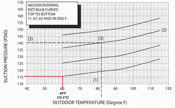
Figure 1.
On a chilly spring day, the refrigeration system may not respond as expected (in this case 116 psig suction pressure) indicating the system may not be ready for a July heatwave. Without sufficient load on the evaporator, too many technicians are liable to alter the refrigerant charge or to replace system components thought to be problematic when the real issue is simply no load.
Spring Conditions
Soon service vans will be loaded with replacement filters, refrigerant, coil cleaner and replacement parts such as run capacitors, contactors and motors. Residential HVAC service departments will have a baseload of equipment service histories and commissioning data related to their own installations. Technicians should familiarize themselves with all collected data including any notes from previous service calls before venturing forth.
Amid the enormous variety of installed equipment in the field, technicians must understand the individual manufacturer’s instructions for determining proper performance especially under minimal load conditions.
Contractors selling maintenance plans as a component part of a new installation have the best opportunity to ready an HVAC system for the rigours ahead. Many a service contractor will altruistically adopt orphaned equipment often consisting of a sub-par installation combined with little or no maintenance creating an entirely different start-up experience for a consumer not used to HVAC repair bills.
A residential start-up routine should have several moving parts: a conference with the end-user, a visual inspection of the entire system, cleaning components and replacing consumable items, then testing and data collection.
Data collected from an end-user interview consists of asking questions related to unusual occurrences such as different noises, problems during the heating season, odours or water leaks.
The homeowner might reveal severe system deficiencies like poor heat distribution that may or may not fit the spring tune-up protocols of clean, inspect and test.
If cleaning a blocked evaporator coil has little effect on improving air flow to the master bedroom, then another service call should be scheduled to investigate that common problem.
Order of Operations
After the customer interview, check for a communicating or smart thermostat controlling the system. Look for stored faults or alert codes especially reoccurring faults such as flame failure, open limits and communication errors. How were past issues resolved, and why have one or more reoccurred?
Such faults provide clues as to what maintenance is required. See if the thermostat has a monthly record of operating hours; plenty of clues to be found there. In Figure 2, a graphical display of my HVAC needs is presented for the year 2019. In my case, during the summer I keep the room at 75F (24C) although the system will operate in dehumidification mode when the RH exceeds 55%.
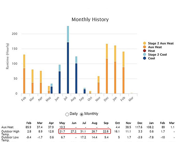
Figure 2.
Notice that I used a total of 34 hours of cooling capacity (mostly first stage) in the month of May, while the heat and humidity of July caused the system to run a total of 227 hours, just 54.4 hours in second stage. To my point, the system ran a total of 504 hours in 2019, or roughly 6% of the time.
Indoor Unit Inspection
Disconnect power to the air handler then visually inspect the unit looking for signs of refrigerant leaks, water leaks, loose wiring, blower wheel condition, and evaporator coil cleanliness. Be sure DIP switches, interface settings, and motor wiring taps are set-up correctly to coincide with outdoor unit capacity or the AHRI certified rating.
During the air handler inspection, the test of any maintenance contract might come to the bare coverage as the time and materials needed to thoroughly clean an evaporator coil, blower wheel, secondary heat exchanger, drain assembly and to verify settings could easily run into several hours, not normally part of the contract.
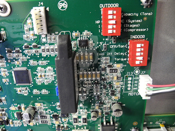
Figure 3a)
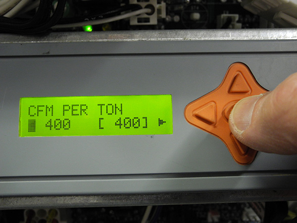
Figure 3b
Depending on the manufacturer, there might be numerous settings to verify when servicing an orphaned unit with no service history (see Figures 3a & 3b).
As the images in Figure 4a and 4b show, evaporator coils must be inspected and cleaned where possible.
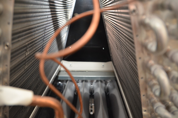
Figure 4a
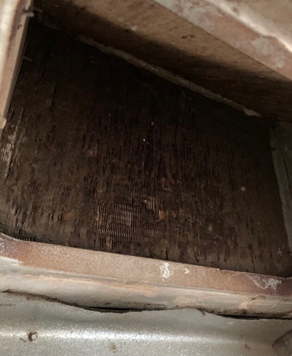
Figure 4b (photo: Markus Berger)
The condensate drainage system must be ready to handle condensate (Figure 5). Some drains are too small or use non-standard components. Blow out the drain lines, clean condensate pumps and test operation.
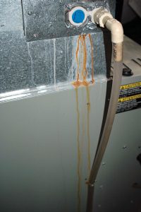
Figure 5
Always inspect the blower wheel in conventional air handlers and mini splits (Figures 6a&b, below). The indoor head may have to be removed for cleaning, or the coil may be cleaned in place if the blower wheel is clean. Be sure to clean or supply a new air filter.
Some indoor tune-ups could turn into overhaul or system replacement situations. Apprise the customer and leave a quote for additional services.
Once the myriad of vital components has been inspected, settings verified and necessary cleaning completed, reapply power. Observe the furnace control board for any flashing fault codes. Older boards will not remember faults: check for codes before de-energizing.
Some units have a user interface containing stored faults, recover and analyze data concerning faults. Check for voltage at the control board Line H and Line N connections as well as low voltage transformer output.
Put the indoor unit into operation in a test mode (if available) or “fan on” mode listening for anything unusual. Verify voltage at the board and test the fan motor amperage. Be sure to record this data.
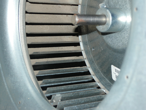
Figure 6a
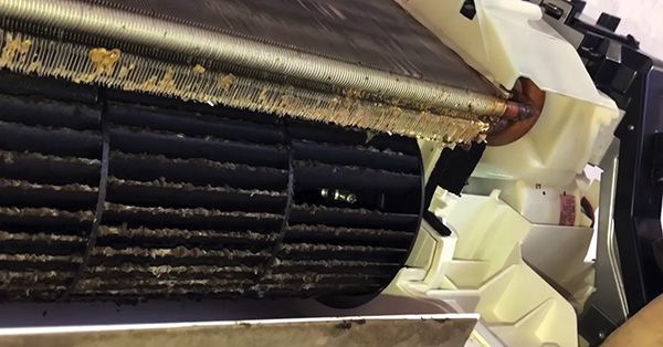
Figure 6b
Outdoor Unit
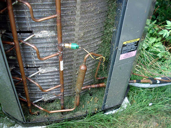
With all power sources disconnected from the outdoor unit, begin inspection of key components including the outdoor coil, refrigerant line set, signs of refrigerant leaks, electrical connections, condenser fan motor and blade, and cabinet integrity.
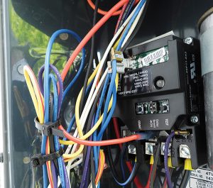
Figure 7
Clean outdoor units of rodent nests and bug intrusions. Consider offering a contactor upgrade such as Emerson’s Sure Switch (Figure 7) featuring totally enclosed contacts providing brownout and short cycle protection.
Visually inspect components such as capacitors and look for copper tube rubs, pinched wires and high voltage connections. If the compressor has a starting capacitor, inspect all electrical connections and capacitor integrity. If any starting components must be replaced, use only manufacturer approved components.
All electrical connections, low and high voltage, indoor and out must be inspected for damage, overheating, and tight connection. Low voltage spade connections are often overlooked. Remember to check inside the outdoor disconnect box for debris, corrosion and loose connections, critter infestations, etc.
Once the clean and check is complete, restore power and start the system to operate at 100% capacity, use thermostat test mode if so equipped.
Allow the system to operate for a minimum of 15 minutes at the appropriate test load parameters before taking system data.
The following information is the minimum requirement to establish a year-over-year performance history:
- Temperature of the air entering the indoor coil: dry bulb and wet bulb.
- Temperature of the air leaving the indoor coil: dry bulb and wet bulb.
- Temperature of the air entering the outdoor coil: dry bulb.
- Suction Pressure.
- Suction Line Temperature.
- Head Pressure.
- Liquid Line Temperature.
- Discharge Line Temperature.
- No Load Volts.
- Full Load Volts.
- Full Load Amps.
- Lock Rotor Amps.
- Crankcase Heater operation, if equipped.
Note: premium units, typically featuring inverter drive compressors, have on-board or other methods of displaying much of the above data; it should be downloaded and archived.
Using this collected performance data, a technician can make objective judgements as to the system’s capabilities during the cooling season ahead.
So far, I have not mentioned airflow, the most important parameter of all. When analyzing entering and leaving wet bulb data, total Btu/h of the system can be determined to a reasonable degree of accuracy provided the actual system airflow is known—guessing or plugging-in nominal values is not allowed!
Do a temperature rise test, or measure air pressure drop across the air filter or evaporator coil provided the numbers obtained coincide with the chart provided by the device manufacturer. Once an accurate measure of airflow has been recorded, use the following formula to determine system Btu/h: for this example, a cooling unit with a nominal AHRI rated cooling capacity 23,850 Btu/h is being evaluated (Figure 8).
Btu/h = 4.5 x Actual Airflow x ∆H
Suppose an entering wet bulb is 56F and the leaving wet bulb is 45F. Use a psychometric chart to convert 56F Wb to 23.85 Btu/pound of air and 45F Wb to 17.69 Btu/pound. Airflow is measured at exactly 800 cfm. How does this measured value compare with the manufacturer’s chart for system performance at a given outdoor temperature? Is the value close enough?
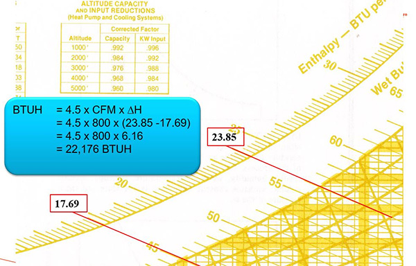
Figure 8
Assuming, at seasonal start-up, the collected values mirror a manufacturer’s performance data chart and industry standards, this information should be recorded on a copy of the job ticket and left with the equipment; the HVAC system also owns this data, in my view.
Whether a residential service call entails simple maintenance, or an unfortunate breakdown, or leads to a potential system replacement opportunity, having reliable performance data included in the service history eliminates vexatious guesswork and assumptions leading to faster, more accurate, customer service. <>
 Ian McTeer is an HVAC consultant with 35 years of experience in the industry. He was most recently a field rep for Trane Canada DSO. McTeer is a refrigeration mechanic and Class 1 Gas technician.
