
Fixing the Fix
December 15, 2020 | By John Siegenthaler
In this case the pressure relief valve (PRV) did just what it was supposed to do—relieve rapidly increasing pressure inside the boiler before that pressure could be released in a far more dramatic and perhaps “explosive” manner.
(Getty Images)
Have you ever been involved with a project where a “fix” for one situation created a “glitch” elsewhere? I suspect that many of you can answer in the affirmative. In most cases the “glitch” forced another modification that – hopefully – solved both it and the original problem. This month’s article is all about one such scenario.
Some Background
In past articles I’ve discussed the advantages, and limitations, of “two-pipe” buffer tank configurations, especially as they relate to biomass boiler systems. Figure 1 (below) shows a typical two-pipe configuration for reference.
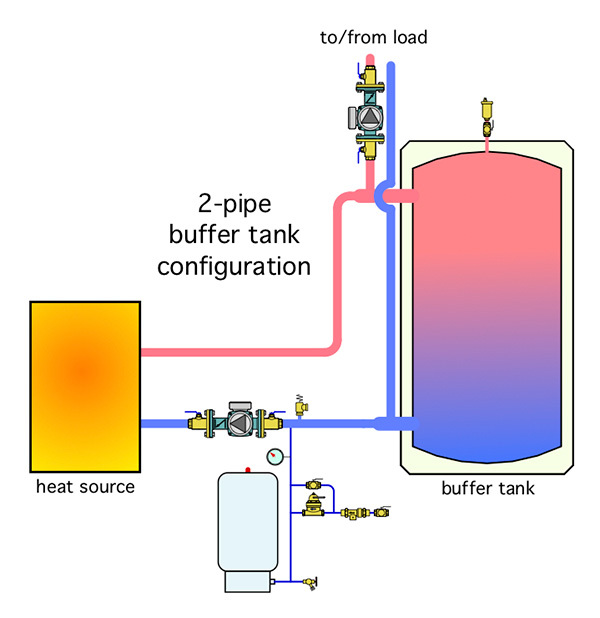
Figure 1. Two-pipe buffer tank configuration.
The advantages of a two-pipe buffer tank configuration are:
- Heated water can move directly from the heat source to the load without first passing through the buffer tank when the heat source and load are operating at the same time.
- When the conditions described in 1. above are present, the flow rate into and out of the buffer tank is only the difference between the heat source flow rate and the load flow rate. Lower flow rates into and out of the tank reduce mixing and help preserve beneficial temperature stratification.
The “Achilles heel” of a two-pipe buffer tank configuration is that it’s possible, when appropriate measures are not taken, for some of the flow returning from the load to pass through the inactive heat source rather than through the buffer tank. This creates heat loss in the mechanical room and also reduces the supply water temperature to the load.
Preventing this undesirable “ghost flow” through the inactive heat source(s) requires hardware that can create a suitable pressure threshold before forward flow is allowed.
One way to do so is to install a motorized two-way valve that closes when the heat source is off, and opens when it’s operating.
On one project that I’m familiar with these motorized two-way valves were added as a last-minute means of preventing flow through any of three pellet boilers when they were not operating. The valves were signaled to open when the boiler’s circulator turned on, which, based on internal controls in each pellet boiler, would not occur until the boiler water reached some initial temperature indicating that the combustion was established and stable.
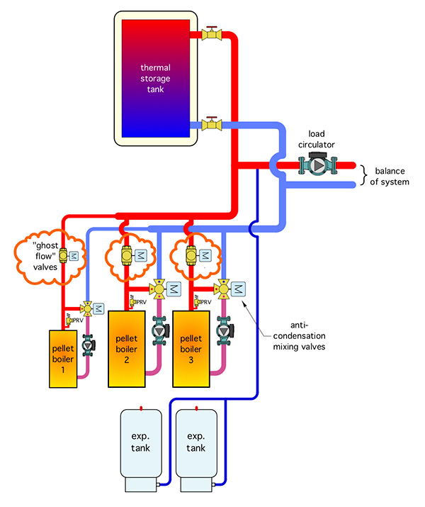
Figure 2.
Figure 2 (above) shows where these “ghost flow” valves were added.
In this system, each pellet boiler has a motorized three-way that serves as an “anti-condensation” mixing valve. The cool water inlet port of this valve is fully closed until the inlet of the pellet boiler reaches a temperature of 130F.
If the water temperature in the boiler continues to rise, as it should, the cold port of the valve continues to open allowing increasing flow from the boiler to the load. If the return water temperature drops back toward 130F the cold port of the valve decreases cool water flow into the valve in an attempt to keep the inlet water temperature high enough to prevent sustained flue gas condensation within the boiler.
Study the details in Figure 2 carefully. Do you see any issues?
If not, here’s a clue: as a boiler warms up fluid begins to “dribble” from its pressure relief valve (PRV). This occurs well before the water in the boiler reaches 130F.
What’s Happening?
I’m sure some of you spotted the problem. During a cold start the anti-condensation valve is in full bypass. This effectively blocks the piping path from that valve’s cool port to the balance of the system.
The motorized “ghost flow” valve is also closed until the boiler warms up. Because this valve was installed on the supply pipe from the boiler it also blocks any “pressure communication” between the boiler and the balance of system, where the expansion tanks are located.
The result is a volume of incompressible fluid being heated without any communication with the system’s expansion tank. Under those conditions the PRV did just what it was supposed to do—relieve rapidly increasing pressure inside the boiler before that pressure could be released in a far more dramatic and perhaps “explosive” manner.
If the ghost flow valves had been installed on the boiler’s return pipe this problem would not arise.
The pressure inside the boiler could communicate with the system’s expansion tank through the boilers outlet pipe. Unfortunately, this detail was not spotted prior to the installation of the ghost flow valves.
The Fix
There are a couple of potential ways to fix this situation. One would be to see if the actuator on the anti-condensation valve could be adjusted so that the cold port was never 100% closed. This might or might not be possible depending on the actuator and valve used.
Fortunately, there was a pressure-testing tapping installed on each side of each ghost flow valve. One of those tappings was equipped with a small ball valve. This allows a very short length of ¼-in. copper tubing to be installed as a pressure equalizing tube around the closed ghost valve as shown in Figure 3 (below).
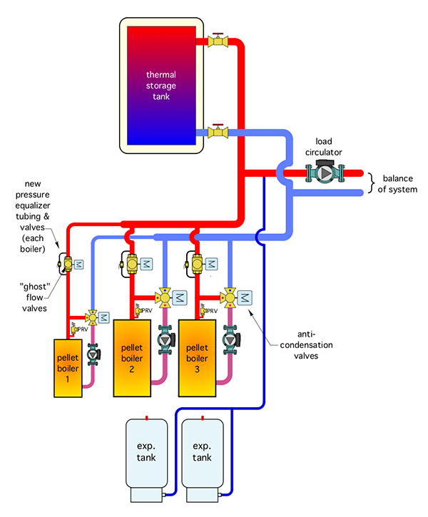
Figure 3.
The ball valve in the pressure equalizer tube is cracked open very slightly to minimize flow rate through the bypass while still allowing the expanding fluid to reach the system’s expansion tank.
Once set, the handle of the ball valve was removed to reduce potential for tampering.
I recommended this solution because in an emergency replacement situation, a technician may not realize that the actuator of the replacement anti-condensation valve requires an adjustment to prevent the cold port from being fully closed. Without such an adjustment the problem would reoccur. There’s also a possibility that the replacement parts might not allow such an adjustment.
The fix of the fix resolved a dribbling PRV situation. It also prevents flow returning from the load from passing through inactive boilers.
The take-away: Always check your piping layouts to ensure that any heat generating equipment can never be isolated from “communication” with the system’s expansion tank. The same goes for chillers. <>

John Siegenthaler, P.E.

