
Keep heat produced by auxiliary boilers out of thermal storage
December 13, 2018 | By John Siegenthaler
Most hydronic heating systems that have renewable energy heat sources, such as solar thermal collectors, an air-to-water or geothermal heat pump, or a biomass boiler, also have an auxiliary boiler. Many of these systems also have one or more thermal storage tank(s) that absorb excess heat when it is available from the renewable heat source, and park it for later use. The thermal storage tanks used in systems with solar thermal collectors and biomass boilers often contain several hundred of gallons of water.
The auxiliary boiler can be treated as a backup to the renewable energy heat source. If the renewable energy heat source is unable to provide any useful heat to the system the auxiliary boiler provides all the heat the system requires. This implies that the auxiliary boiler must be sized to handle the system’s full design load.
The auxiliary boiler can also be treated as a supplemental heat source. This refers to a situation where the renewable energy heat source is providing some of the heat the system requires, while the auxiliary boiler provides the remainder. In this capacity the auxiliary boiler would not necessarily be sized to handle the system’s design load.
In either of these roles it is important the auxiliary boiler operates only when necessary. It is also important that heat produced by the auxiliary boiler flows directly to the load rather than into thermal storage.
The rationale for the latter is based on the second law of thermodynamics. Fuels such as natural gas, fuel oil or electricity are “high grade” energy. It is easy to store high grade energy for long periods of time without degradation. However, when high grade energy is converted into heat, which at the temperatures needed for space heating is a relatively low-grade energy, storing it for more than a few hours is difficult and expensive.
Think about this. If a 500-gallon tank contained water at 150F, and was located in a room at 70F, how long could the heat it contains be stored?
In theory, and regardless of how well insulated that tank was, heat would immediately begin “leaking” out of the tank. The insulation system on the tank would affect the rate of heat loss, but no insulation system can totally stop heat transfer as long as there is a temperature difference between the inside and outside of the tank. The moral: Do not use high grade energy to keep a thermal storage tank at an elevated temperature while waiting for a load that eventually needs that energy.
THIS DOES HAPPEN
One of the undesirable characteristics that I’ve witnessed on several systems with renewable heat sources is an inadvertent set of circumstances where heat created by the auxiliary boiler ends up in the thermal storage tank.
In one system that I had opportunity to visit the thermometer on a 700-gallon thermal storage tank associated with a pellet boiler showed an internal temperature of 145F. That, in itself, is not a problem. However, it became a problem when the person responsible for the system told me that the pellet boiler had not operated in over a month due to a maintenance issue.
So how was the tank maintaining that elevated temperature when the boiler intended to heat it had been off for a month? Answer: a 3-phase electric auxiliary boiler.
The building automation system that staged the pellet boiler and auxiliary electric boiler did not “understand” that the pellet boiler was not operating. It kept the circulator between the thermal storage tank and distribution system operating and supplied heat to the system from the electric boiler, which was treated as a second stage heat source. The water returning from the distribution system flowed in and out of thermal storage and thus unnecessarily maintained it at an elevated temperature. While it’s arguable that this does not damage the system it certainly adds to uncontrolled heat loss into the mechanical room.
This inadvertent condition is usually the result of a controls that treat the renewable heat source portion of the system as fixed first stage heat input, and the auxiliary boiler as the second stage heat input. That is how a typical tandem boiler system would be controlled, and thus it is how many control systems would be routinely configured.
In most cases the controls just assume that both stages of heat input are available to contribute heat to the system whenever necessary. The controls do not necessarily verify if this “assumption” is valid. If the first stage heat source cannot provide the necessary supply water temperature to the distribution system, the controls activate the second stage heat source. The first stage heat source remains active. (The “go” signal to the first stage heat source is on and so are any associated circulators that move water through that heat source).
This is not a “big deal” when two identical boilers serve as the first and second stage heat inputs. However, when a large thermal storage tank is involved there is much greater potential for uncontrolled heat loss due to its high surface area. Furthermore, if the circulator between that tank and a biomass boiler remains on when that boiler is not producing heat, the boiler’s jacket and air flow through the combustion chamber increase uncontrolled and undesirable heat loss.
THIS DOES NOT NEED TO HAPPEN
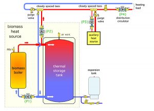
Figure 1
There is a relatively easy and inexpensive way to prevent this undesirable condition. To understand it, consider a system that uses a biomass boiler and its associated thermal storage tank as the first stage heat input.
Think of the biomass boiler and thermal storage tank as a single entity that we will call the “biomass heat source.” Heat supplied from this entity might come directly from the biomass boiler(s), or from thermal storage, or from both. It depends on the firing status of the biomass boiler(s) and the status of the load(s).
The “biomass heat source” is treated as a fixed lead heat source to the distribution system, in combination with and auxiliary boiler as the second stage heat source, as shown in Figure 1.
The “biomass heat source” is connected to the distribution system using a pair of closely spaced tees. This provides hydraulic separation between circulator (P2) and the distribution circulator (P4). Circulator (P2) could be a fixed speed circulator or as variable speed injection circulator. The latter allows it to regulate the supply water temperature of the distribution system.
The auxiliary boiler is also connected to the distribution system using a pair of closely spaced tees for hydraulic separation. These tees are located downstream of the tees that connect the biomass heat source to the system. This arrangement allows the thermal storage tank to contribute heat to the distribution system at lower temperatures than would be possible if the tees for the auxiliary boiler were upstream of those from the biomass heat source.
POSITIVE CONTRIBUTIONS ONLY
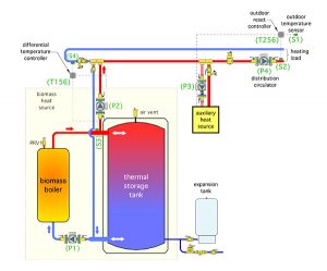
Figure 2
The key to preventing inadvertent transfer of heat produced by the auxiliary boiler into thermal storage is comparing the temperature of the water returning from the distribution system to that at the upper tank header. As long as the temperature at the upper tank header is a few degrees higher than the temperature of water returning from the distribution system, the biomass heat source can make a positive energy contribution to the space heating load. This control function is easily handled using a differential temperature controller.
Figure 2 shows a differential temperature controller, labelled as (T156) comparing these two temperatures at sensors (S3) and (S4). Circulator (P2) is only allowed to operate if the temperature at the upper header of the thermal storage tank, at sensor (S3), is at least 5F above the temperature at sensor (S4) on the return side of the distribution system.
This prevents heat generated by the auxiliary boiler, which might elevate the water temperature on the return side of the distribution system, from being inadvertently sent into thermal storage. It also prevents flow from what might be cool thermal storage into the distribution system. If the temperature at sensor (S3) drops to within 3F of the temperature at sensor (S4), circulator (P2) is not allowed to operate.
The on/off temperature differentials of 5 and 3F are only suggested values. They include an allowance for temperature sensing accuracy. To minimize sensing error, it is best to use identical mounting techniques for both temperature sensors.
The outdoor reset controller, labelled as (T256) in Figure 2, turns on the auxiliary boiler and circulator (P3) when and if the water temperature supplied to the distribution system at sensor (S2) falls slightly below the current “target” temperature that can maintain adequate heat delivery to the loads. Using an outdoor reset controller to “decide” when the auxiliary boiler needs to operate allows the biomass heat source to contribute heat to the lowest possible temperature that can still maintain building comfort. That, in turn, allows for longer biomass boiler burn cycles, which improve efficiency and reduce emissions.
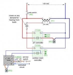
Figure 3 Simple electrical schematic
The controllers shown in Figure 2 are not used to turn the pellet boiler on and off. That function is managed by a controller inside the pellet boiler (or in some cases an external controller) that measures the temperature in the upper and lower portions of the thermal storage tank. The pellet boiler and circulator (P1) are operated to maintain the temperature of the thermal storage tank within a specific range, regardless of whether the space heating load is on or off.
Figure 3 shows a simple electrical schematic that combines the differential temperature controller (T156) and outdoor reset controller (T256) to synergistically manage heat input to the distribution system.
The differential temperature controller (T156), and outdoor reset controller (T256), are energized only when there is a call for space heating. Together, they manage all heat input to the distribution system from the two available heat sources. Heat input from the biomass heat source takes priority whenever possible, but comfort is never compromised. It is “guarded” by the outdoor reset controller and auxiliary boiler.
The combined logic provided by these two controllers, or their equivalent programming within a building automation system, is simple but effective. It prevents the system from “running blind” to a condition where heat from the auxiliary boiler is flowing into thermal storage. <>
 John Siegenthaler, P.E., is a mechanical engineering graduate of Rensselaer Polytechnic Institute and a licensed professional engineer. He has over 34 years experience in designing modern hydronic heating systems. Siegenthaler’s latest book is Heating with Renewable Energy (see www.hydronicpros.com for more information).

