Low Temperature Recirculation
April 12, 2023 | By John Siegenthaler
Strategies for incorporating renewable energy thermal storage with DHW.
Given their intermittent heat generation characteristics, many hydronic-based renewable energy systems require thermal storage. Examples include solar thermal systems and biomass boilers. Thermal storage is also used in heating systems supplied by off-peak electricity and micro combined heat and power (MCHP) systems.
The temperature of the thermal storage tank can vary over a wide range. If supplied by a solar thermal collector array, and following two or three sunny days with minimal loading the tank temperature could be upwards of 180F.
These temperatures are also possible at the end of a tank “charging” cycle from a biomass boiler, as well as in off-peak electric thermal storage and MCHP systems.
At other times, when there’s little if any heat input from the renewable energy heat source, the thermal storage tank could cool down, even down to the surrounding air temperature.
This wide temperature variation implies there will be times when thermal storage could supply all the energy needed to heat domestic hot water (DHW) to a typical maximum delivery temperature of 120F.
Heat would be passed from the “system water” in the thermal storage tank to DHW through a stainless steel heat exchanger. There will also be times when thermal storage could only preheat DHW, and another heat source would “top off” the water to the required delivery temperature.
Leveraging Low Temperatures
Even though preheating doesn’t bring DHW all the way to the final temperature, it’s importance shouldn’t be underestimated.
It takes as much energy to bring a quantity of water from 50F to 60F, as it does to bring it from 150F to 160F.
Thermal storage tanks, even at reduced temperatures, can “leverage” the low end of the temperature rise. Because of this, domestic water heating, where it’s needed, is an enticing load to combine with renewable energy heat sources.
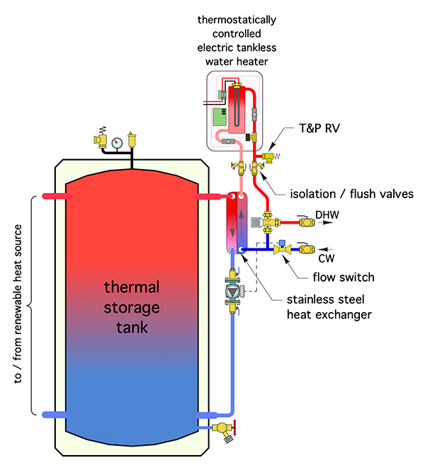
Figure 1.
Figure 1 (above) shows heat from thermal storage transferred to DHW using a single pass stainless steel heat exchanger.
A flow switch closes its contacts when it detects a specific minimum flow rate of domestic water, typically around 0.5 to 0.7 gpm. This turns on a circulator that routes water from the upper portion of the thermal storage tank through the primary side of the brazed plate stainless steel heat exchanger. Heat is transferred to “cold” domestic water entering the secondary side of the heat exchanger.
Brazed plate heat exchangers have a high ratio of internal surface area to fluid volume and respond very quickly to temperature changes. With the heat exchanger and circulator located as close as possible to the tank to minimize piping length, the response time from when the flow switch closes to when heated domestic water emerges from the secondary side of the heat exchanger should be about 3 to 5 seconds.
A thermal storage tank at 95F could potentially heat domestic water from 45F to 90F. That’s 60% of the temperature rise, and 60% of the energy required to fully heat the water from 50F to 120F.
A thermostatically-controlled electric tankless water heater provides the final temperature rise, when required.
If the DHW enters this heater at or above the required delivery temperature, the elements in the heater do not turn on.
An American Society of Inspectors of Plumbing and Sanitary Engineers “ASSE 1017” listed thermostatic mixing valve provides protection against high DHW delivery temperature in situations where the thermal storage tank is at an elevated temperature.
Add a Loop
The system in Figure 1 doesn’t ensure that DHW, at the required temperature, is instantly available at every fixture. That requires a recirculation piping system.
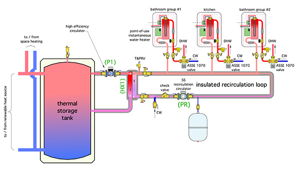
Figure 2.
The system in Figure 2 (above) adds a recirculation loop, along with several point-of-use electric tankless water heaters to the heat exchanger/circulator subassembly shown in Figure 1.
Each point-of-use tankless heater draws heated water from the recirculation loop. A typical system would use one tankless heater for each bathroom group (shower/tub and lavatory), and it would use separate tankless heaters for the kitchen, laundry or other areas where DHW is required.
Each tankless heater would be sized to the flow and delivery temperature requirements of its fixture group. Each would be controlled by its internal thermostat so only the energy necessary is added to the preheated water.
If the entering water is already at or above the required temperature the elements within these heaters remain off. An ASSE 1070 listed thermostatic mixing valve ensures that the water delivered to the fixtures doesn’t exceed a safe delivery temperature.
A small stainless steel recirculation circulator moves water around the loop whenever DHW may be required in the building.
This is not necessarily 24/7.
Another small high-efficiency circulator maintains flow between the storage tank and stainless steel heat exchanger.
Assuming an upper tank temperature of 120F, a high efficiency circulator between the tank and a 5-in. x 12-in. x 50 plate heat exchanger could yield an output of 4 gpm of domestic water heated from 50F to 115F with a power input of about 30 watts.
A small recirculation circulator would add another 12 watts of power input.
If both circulators ran continuously in a location where electricity costs $0.15 per kWh, the operating cost would be about $0.15 per day. This could be reduced by turning off the recirculation system during times with little or no expected demand for DHW.
Even when the recirculation system is off, each tankless heater can provide some hot water to its associated fixture(s) with energy being supplied solely by electricity. The flow rate and delivery temperature would depend on the power rating of that heater.
The check valve downstream of the recirculation circulator forces domestic cold water through the heat exchanger whenever hot water is drawn from any fixture. This approach has several advantages.
First, the power requirement of each tankless heater is only for the fixture group it serves. For example, a 7 kW tankless heater would provide up to 1.9 gpm flow rate with a corresponding temperature change from a “preheat” temperature of 95F, to a delivery temperature of 120F. A 7 kW tankless heater could be supplied from a 240 VAC/30 amp circuit. Higher capacity tankless heaters could be used where higher flow rates are needed.
Second, multiple tankless units provide redundancy relative to a single higher capacity heater.
Third, when water in the recirculation loop is at a lower temperature, heat loss from the loop is reduced. Still, the recirc loop should always be insulated.
Kill the Bugs
Any DHW system operating at temperatures in the range of 68F to 122F has the potential for legionella bacteria growth.
Tempered water between 77F and 113F provides an optimum growth environment.
To address this, the system from Figure 2 has been further detailed with a dedicated thermal sterilization tankless heater, as shown in Figure 3 (below).
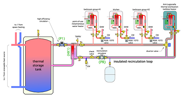
Figure 3.
The purpose of the sterilization heater is to periodically elevate the water temperature in all portions of the recirculation loop high enough—and maintain that temperature long enough—to kill Legionella bacteria.
In the absence of specific codes that require otherwise, typical daily thermal sterilization temperature/cycle durations are as follows:
- 158ºF (70ºC) for 10 minutes
- 149ºF (65ºC) for 15 minutes
- 140ºF (60ºC) for 30 minutes
Some electric tankless water heaters can heat water as hot as 180F, while others have internal safety switches that prevent temperatures above 140F.
The sterilization cycle could be programmed to occur at times of no DHW use, such as early morning hours.
If one assumes no DHW draws during this relatively short sterilization cycle the power output of the sterilization heater is only that required to match the heat loss of the recirculation loop.
Here’s an example: assume a DHW loop is 100 feet of 1-in. insulated copper tubing on the supply side, and 100 feet of ½-in. insulated copper tubing for the recirculation piping. Also assume an average water temp in the loop of 155F during the sterilization cycle.
The total heat loss of the piping under these conditions is about 2,700 Btu/hr. Add 20% to account for heat loss from riser piping to fixtures, heat loss from the insulated heat exchanger, and from the recirculation circulator, valves, etc.
The total estimated 3,240 Btu/hr heat loss is just under 1 kW (3413 Btu/hr). One of the smallest available electric tankless heaters (about 3kW) has more than enough capacity to achieve the sterilization requirements.
The ASSE 1070 mixing valves on each fixture prevent scalding temperatures from reaching the fixtures if water is drawn during the sterilization period.
Leveraging Low Temperatures
Due to its low starting temperature, domestic water heating is a very “attractive” load to be supplied by renewable energy heat sources.
This concept takes advantage of the low starting temperature and ensures consistent, safe, and immediate DHW delivery at all fixtures, and minimizes the potential for harmful levels of bacteria to reach any fixture. <>