
Supermarket Compressor Replacements
December 12, 2023 | By Dave Demma
Maintenance and best practices are key to prevent premature compressor failure.

(photo: AJ_Watt/Getty Images)
The vapour compression cycle is the basis for nearly every refrigeration system in use, and the goal for each system is consistent and succinct: provide the correct mass flow and temperature of liquid refrigerant to the inlet of each system evaporator necessary to transfer the required heat load from each space such that the design space temperature can be maintained.
While there can be a great variety between applications, which might necessitate the use of elaborate controls, special components or accessories, each system utilizes the same four major components, each with its own specific (and rather simplistic) function. For review, here’s a simple breakdown:
Compressor: A vapour pump, which receives low pressure vapour and compresses it into a high pressure vapour. The mechanical process of compression adds heat to the vapour, so the discharge leaving the compressor always exits a higher pressure and at a temperature above saturation (superheated).
Condenser: This is one of two heat transfer surfaces present in the system, and its function is to transfer heat from the refrigerant to the atmosphere (in an air-cooled condenser) or a secondary heat transfer fluid (water-cooled condenser). In a properly sized condenser, this will allow the vapour to be transformed from a superheated vapour, to a saturated vapour (desuperheated), then from a saturated vapour to a saturated liquid (change of state), then from a saturated liquid to a subcooled liquid.
Expansion Device: Again, the end goal of the system is to provide a saturated refrigerant at a temperature lower than the refrigerated space so that heat in the space can be transferred to it. As such, the function of the expansion device is to allow for a reduction in liquid refrigerant pressure—to a pressure that corresponds to the particular refrigerant saturation temperature required.
Evaporator: This is the other heat transfer surface present in the system, and its function is to transfer heat from the refrigerated space to the saturated refrigerant flowing through the evaporator. Since the latent heat of vaporization (amount of heat required for a liquid to undergo a change of state to a vapour) is quite high, the majority of the evaporator will have saturated liquid flowing through it to allow for efficient heat transfer. The expansion device will regulate the flow of refrigerant into the evaporator and maintain a minimum amount of superheat at the evaporator outlet, solely to prevent liquid refrigerant from flowing back to the compressor and the resulting compressor damage that it would cause.
Supermarket Systems
Every supermarket chain seemingly has very similar requirements for its refrigeration equipment. However, it is interesting to note that each chain has its own idea of what that perfect system is. Below are some of the more common systems in use, without reference to any particular refrigerant.
Conventional System: One compressor and condenser for each evaporator system. An evaporator system can be described as either a single evaporator, or several evaporators piped in parallel (such as three meat display cases). The method of temperature control is typically a thermostat, controlling either the compressor itself or a liquid line solenoid valve. A large roof mounted condenser, circuited to handle the heat rejection load for several individual compressor systems, may take the place of individual condensers.
Multiplex System: A derivation of the above system, using a single compressor and condenser, but connected to two or more evaporators. Each evaporator’s temperature is independently controlled, either with an evaporator pressure regulator or thermostat and liquid line solenoid valve. As with the Conventional System above, the compressor may be piped to one circuit of a roof-mounted multi-circuited condenser.
Parallel Rack System: This system consists of several compressors of varying capacity connected to common suction and discharge headers. The refrigeration load consists of multiple evaporator systems connected to the common suction header.
In an effort to maintain a minimum common suction pressure, the rack’s energy management system will cycle compressors on/off as required. The term “cycling” may consist of a compressor cycling on/off, or a compressor of one size cycling off while a compressor of another size cycles on.
The rack’s common suction pressure is determined by whichever connect circuit operates at the lowest temperature. Individual circuit temperature is typically controlled with an evaporator pressure regulator (EPR); by maintaining a constant pressure (refrigerant saturation temperature) in the evaporator, or an electric evaporator pressure regulator (EEPR), which responds to, and maintains a very consistent discharge air temperature.
Secondary Refrigerant: This system allows for the greatest reduction in refrigerant charge. A Parallel Rack is still utilized, but its combined capacity is mated with a secondary heat exchanger used to provide a constant flow/temperature of a secondary heat transfer fluid (glycol, CO2, or some other proven heat transfer medium) to the primary heat exchangers (walk-in boxes or display cases).
The heat load from the refrigerated fixtures is transferred to the secondary fluid, which is in turn transferred to the refrigerant via the secondary heat exchanger.
Compressor Complications
Typically, a well-designed refrigeration system has no need of field modification. And, while there are exceptions to every rule, when a compressor replacement is required the replacement compressor should be the same model as the original compressor in use. This will ensure that the compressor rack operates as designed.
There are occasions where the system has been altered, maybe adding/removing display case lineups which would result in a different Btu capacity requirement for the compressor rack. In a circumstance such as this, a discussion with the compressor rack manufacturer would be in order.
Given the four major system components discussed above, the compressor is the heart of the system. Without it, there is no refrigerant flow.
Regardless of whether it’s a reciprocating piston, scroll or screw compressor, if the system is commissioned correctly and undergoes scheduled maintenance the compressor should live a long life.
To provide some “facts” for the above statement, here are some statements regarding failed compressors from various compressor manufacturers:
- Approximately 30% of all compressors pulled from the field, returned to manufacturers, and torn down for failure analyses do not have observable defects. (Copeland)
- 60% to 70% of returned failed compressors are the result of system/service-related issues, or the result of misdiagnosis. (Carrier Corp.)
- 80% of compressors returned for electrical motor failure were system caused by mechanical failures that progressed into an electrical failure. (Carrier Corp.)
- 95% of alleged warranty failures turned out to be caused by external influences from the refrigeration system itself – that is to say the compressor was not at fault. (Bitzer Corp.)
- 0.25% (that’s ¼ of 1%, or 1 out of every 400) of total UK compressor sales resulted in actual valid warranty claims. (Bitzer Corp.)
I could cite more, but you get the general idea: (1) many compressors are misdiagnosed as failed when in fact there is nothing wrong; (2) for many compressors that have suffered a failure in the field, the cause was misdiagnosed; and (3) the rate of compressors that fail during the warranty period due to some kind of manufacturing defect is quite small.
Lesson From the Field
Here’s a poignant illustration of the above statistics: early in my career as an apprentice technician I accompanied a “seasoned” journeyman technician to replace a “failed” compressor.
Some compressors have internal overloads imbedded in the motor windings, which will open when the motor winding temperature exceeds a rating.
The compressor in question would not start due to some situation which caused the motor temperature to increase above the overload rating, and they opened. The technician diagnosed this as a failed motor and made arrangements to replace the compressor.
The owner of the contracting company arrived at the job as the crane was lifting the compressor off the roof. He brought up his “old” Simpson 260 meter and checked the motor for continuity, and he found that the motor winding resistance was per specification.
The motor had cooled down, allowing the overloads to reset (close). Since the compressor replacement had already been approved, and to avoid a situation which exposed the technician’s costly misdiagnosis, the owner instructed us to proceed with the compressor replacement, even though there was nothing wrong with the compressor. It was a system condition which led to the motor winding overloads opening.
Compressor Containment
The potential for a costly compressor replacement in a typical supermarket is great, simply due to the quantity of compressors in use.
I would liken the typical supermarket refrigeration system to a Ferrari, sophisticated and costly.
From an asset management standpoint, it makes sense to invest in regularly scheduled maintenance.
Some of the items of importance to long compressor life include:
Maintain clean condenser coils
- Lower discharge pressure will reduce stress on bearings.
- Lower discharge pressure will reduce motor amperage.
- Lower discharge temperature will prevent oil from decomposing, and losing its lubricating ability.
- Lower compression ratio will allow compressor to operate more efficiently.
Electrical inspection
- Worn motor contactor/starter contacts can cause voltage imbalance, leading to motor failure.
- Loose wiring at breaker or contactor/starter lugs can cause voltage imbalance, leading to motor failure.
- Check compressor motor amperage to ensure it’s operating within spec.
Check oil failure control operation, monitor compressor oil pressure
- Should a compressor suffer low oil pressure, a defective oil failure control will allow the compressor to continue operating, resulting in failed bearings.
- Low oil pressure could be the result of compressor flooding, which damaged the oil pump.
- Low oil pressure could be the result of excessive bearing clearance (worn bearings).
- Low oil pressure might be the result of liquid refrigerant in the oil.
Notate oil condition
- Discolored oil is the result of overheating. Overheating will reduce the oil’s lubricating ability and also produce harmful contaminants in the system.
- Yearly oil analysis will reveal whether there are harmful chemical contaminants, moisture, or metal components in the oil—all the symptom of a system problem.
Maintain clean evaporator coils
- A dirty evaporator coil will reduce heat transfer efficiency and lead to issues maintaining temperature.
- More importantly, the reduced heat transfer efficiency can result in liquid floodback, which can result in severe compressor damage.
Monitor pressure loss across filters and filter-driers
- A partially plugged liquid filter-drier may not be directly responsible for a compressor failure, but it will result in starving expansion valves. This might cause a technician to change expansion valve settings to reduce the superheat set-point, which could result in floodback once the plugged filter-drier has been replaced.
- Excessive pressure drop in a suction filter can reduce suction vapour velocity to the point where oil return is impeded.
- Excessive pressure drop in a suction filter will cause compressors to operate at a higher compression ratio, reducing efficiency and increasing discharge temperature.
- A plugged oil filter can inhibit the flow of oil from the oil separator/reservoir to the compressors.
Root Causes
When a compressor suffers a failure it is of the utmost importance to determine the root cause of failure.
Another case in point: a service call revealed an inoperative compressor due to a tripped circuit breaker. After ensuring that the crankcase had no liquid refrigerant in it, the circuit breaker was reset.
The breaker immediately tripped.
The three-phase power supply to the compressor motor terminals was disconnected, and the motor windings were checked to see if they were shorted to ground. Using a volt-ohm meter it was verified that they were.
The compressor and compressor contactor were replaced. Liquid and suction filter-driers were replaced. The motor voltage and amperage were checked. Same with the oil pressure.
After the replacement job was finished, the new compressor appeared to be operating properly.
Well then, it must have just been a bad motor.
A thorough investigation and compressor autopsy revealed the root cause of failure:
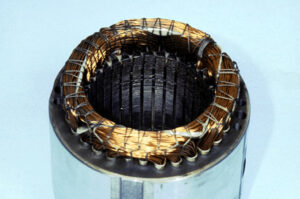
Damaged rotor.
Why did the motor short? The compressor’s main bearings had failed, causing the motor stator to drop, make contact with the rotor, and absolutely destroy the motor windings.
Why did the main bearings fail? The compressor crankcase was full of sludge, which partially plugged the crankcase oil pump inlet screen. This resulted in a loss of lubrication.
Why didn’t the oil failure switch prevent the compressor from operating with low oil pressure? Well, it seems this system had suffered repeated oil failure trips. One creative technician decided these were simply “nuisance” oil failure trips. To eliminate the “nuisance”, he jumped the L and M terminals in the oil failure control, preventing it from ever opening the control circuit.
So, the compressor was allowed to operate during periods of low oil pressure, causing the main bearings to fail.
Eventually, this allowed the stator to drop down, make contact with the rotor and destroy the windings.
The seeming root cause of this failure is the loss of lubrication, which can be answered by the sludge which partially plugged up the pump inlet screen.
Where did the sludge come from? This is the real root cause of the failure.
This can be blamed on; (1) the thermodynamic properties of R-22, which result in high discharge temperature in low temp. refrigeration applications; and (2) lack of preventative maintenance, which resulted in a dirty condenser, leading to higher than normal discharge temperature.
The high discharge temperature caused the mineral oil to decompose, forming sludge, and … well, you know the rest of the story.
Moral of the story: an autopsy is absolutely imperative to prevent repeat compressor failures. <>
 Dave Demma holds a degree in refrigeration engineering and worked as a journeyman refrigeration technician before moving into the manufacturing sector where he regularly trains contractor and engineering groups. He can be reached at ddemma@uri.com.
