
The Right Mix
August 1, 2023 | By John Siegenthaler
Taking a look at common mixing techniques to keep closed-loop water temperature at optimal levels.
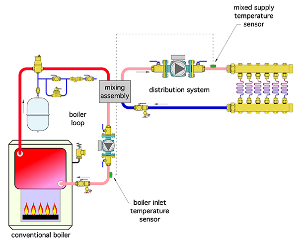
Figure 1. This example of a “mixing assembly” creates a bridge between a boiler loop and the distribution system.
There are many hydronic heating systems where the temperature of water from the heat source is (or might be) well above the temperature required by the heat emitters. Radiant floor heating supplied from a “conventional” boiler is probably the most common example. Although some installers might assume the solution is to turn down the high limit temperature setting of the boiler, that’s not the answer.
The North American hydronics industry learned this lesson the hard way when radiant floor heating began its “resurrection” in the early 1980s. Many boilers, along with their venting systems, were trashed due to sustained flue gas condensation caused by operation at low water temperatures. Turning down the heat source temperature also doesn’t apply to “wild” heat sources such as thermal storage tanks heated by solar collectors, pellet boilers or cordwood gasification boilers.
Fortunately, there are many proven methods of interceding between higher temperature hydronic heat sources and low temperature distribution systems. They are all based on mixing hot water from the heat source with cooler water returning from the heat emitters.
The proportions of that blend can range from 0 to 100% of the hot water. In most cases the blended supply water temperature is between these two extremes.
Two Objectives
The “primary” objective of mixing is to create a suitable supply water temperature for the heat emitters. However, when any type of conventional boiler (e.g., one not intended to operate with sustained flue gas condensation), serves as the heat source, the mixing assembly must also protect that boiler against conditions that would cause that condensation.
The only consistent way to prevent sustained flue gas condensation is to sense and react to the temperature of water entering the boiler.
The sensing part of this requirement is easy — just add a sensor to the pipe leading into the boiler.
The “reaction” part of the requirement is a bit more involved. It requires piping design that allows the boiler to be thermally “uncoupled” from the load when necessary.
I like to describe this function as a “thermal clutch.” To understand the clutch analogy, think about the function of a clutch in a vehicle. It allows the engine to be mechanically uncoupled (fully or partially) from the drivetrain when necessary.
When fully uncoupled, the engine can quickly increase its power output, and not be “lugged down” by a significant mechanical load, such as starting to move a five-ton truck up an inclined road. Once the engine’s power level has increased, the vehicle’s clutch is slowly actuated to begin transferring the engine’s power to the drivetrain. Those who drive vehicles with clutches quickly learn how to control the clutch pedal so as not to overload the engine.
Mixing assemblies that act as a thermal clutch must have the “intelligence” to allow heat to move from the boiler to the load, but not at a rate that would thermally overload the boiler, causing its temperature to drop and creating conditions that cause sustained flue gas condensation.
Building Bridges
The best way to understand different approaches to mixing is to consider a generalized piping design that’s adaptable to several mixing hardware configurations. Figure 1 (above) shows this “mixing assembly” concept that creates a bridge between a boiler (or other heat source) and the distribution system.
The mixing assembly is the only path for heat to move from the heat source to the load. As such it can prevent heat flow, allow heat to cross at the maximum output, or regulate heat transfer between those two limiting conditions.
The mixing assembly is “informed” by two temperature sensors. One on the supply side of the system and the other near the boiler inlet.
Figure 2 (below) shows several hardware configurations that would fit into the conceptual box called the mixing assembly.
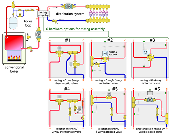
Figure 2. Several potential mixing assembly configurations.
Each configuration connects to the boiler loop at two points (labelled A and B), and also to the distribution system at two points (labelled C and D).
There are several hardware groupings that can be used as the mixing assembly (also shown in Figure 2).
All of these mixing assemblies can provide supply temperature control as well as anti-condensation protection for a conventional boiler. However, some are more “practical” than others.
Of the six mixing assemblies shown we’ll discuss two-way, three-way- and four-way motorized valves, and variable speed injection mixing.
Two-way motorized valves
A two-way motorized valve, piped as shown in assembly #5, allows for injection mixing. The motorized valve meters hot water from the boiler loop into the distribution system. Mixing occurs in the tee downstream of the valve.
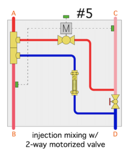 The amount of flow passing through the valve is regulated by an electronic controller that monitors both the supply water to the distribution system and the water returning to the boiler.
When the latter is low enough to allow sustained flue gas condensation (typically below 130F), the controller operates the motorized valve to limit the amount of hot water passing into the distribution system.
This monitoring and adjustment continues as long as the distribution system is active. It keeps the boiler inlet temperature at or slightly above some minimum temperature setting on the controller whenever possible.
The globe valve shown between the tees near points C and D is adjusted so that the two-way motorized valve is fully open while yielding the required supply water at design load conditions.
Notice that the supply temperature sensor for the mixing assembly is located downstream of the tee where the hot and cool fluids mix.
That sensor should be at least four feet downstream of the tee. This is an important detail that ensures the hot and cool water streams are fully mixed by the time the flow passes the sensor.
Although not shown in Figure 2, locating the supply temperature sensor downstream of several fittings, or the distribution circulator when possible, further ensures complete mixing before temperature sensing.
Most controllers that operate a two-way motorized mixing valve output either a “3-wire floating” signal, or a 2-10 VDC modulating signal, depending on the type of actuator used on the valve.
These controllers would also be able to adjust the valve to supply the distribution system with either a fixed setpoint supply temperature, or a temperature based on outdoor reset.
Three-way motorized valves
One of the most common and long-established mixing methods used in lower temperature hydronic systems is based on a three-way motorized valve.
These valves combine hot water from the heat source with cooler water returning from the heat emitters to create a supply water temperature based on either setpoint or outdoor reset control.
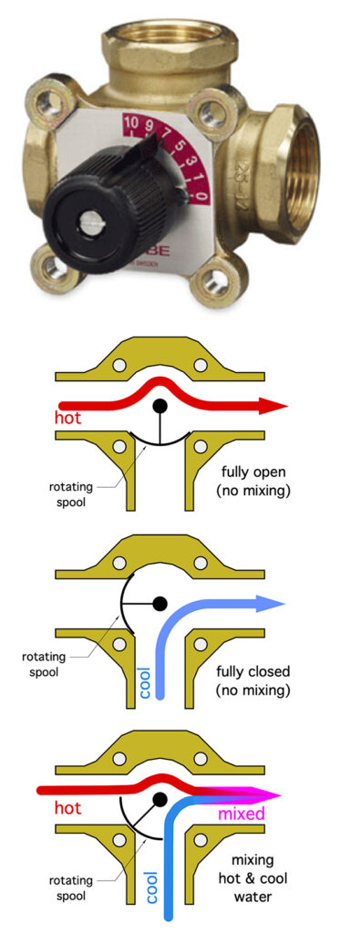
Figure 3. Example of a manual rotary type valve used for three-way mixing.
The controller operating the valve could be identical to that used for a two-way motorized valve. That controller would also monitor boiler inlet temperature and reduce the hot water entering the valve, when necessary, to prevent sustained flue gas condensation.
Figure 3 shows an example of the rotary type valve used for three-way mixing. The valve is shown with a manually adjustable knob which would be replaced with a motorized actuator for automatic control.
The valve has an internal spool that rotates with the shaft. The spool’s position determines the proportions of hot water and cooler return water that enter the valve and mix together.
One extreme position allows no return water into the mix, and the other extreme position allows no heat source water into the valve.
The full range of rotation between the two extreme positions is 90 degrees. Most actuators used to rotate the valve shaft require from 1.5 to three minutes to move the shaft through its full range of travel. Although this probably seems slow, it allows for smooth, stable, and accurate control of the supply water temperature.
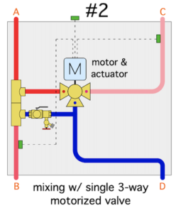
Assembly #2 shows how a three-way motorized valve would be combined with other fittings and a purging valve to form a mixing assembly.
Four-way motorized valves
These valves are specifically designed to create two mixing points within a single valve body. One mixing point regulates the supply water, the other boosts the water temp. entering the boiler.
Figure 2 (assembly #3) shows how a four-way mixing valve is piped. In many ways a four-way motorized valve is functionally equivalent to a three-way motorized valve.
However, there’s one important distinction. If the four-way valve is used with a low flow resistance boiler (such as one made of cast iron sections), AND if the valve is mounted close to the boiler, AND if the boiler is operated at a relatively high temperature (such as 170-200F), it’s possible to eliminate the heat source circulator.
The momentum of the flow returning from the load circuit is sufficient to carry the necessary flow through the boiler. When these unique conditions are present, eliminating the boiler circulator saves first cost and life cycle cost.
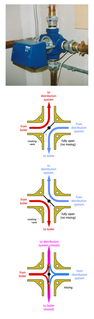
Figure 4. An example of a four-way mixing valve with attached motor actuator.
Figure 4 shows a four-way mixing valve with attached motor actuator.
Variable Speed Injection Pumps
The concept of using a circulator to inject hot water from a heat source into a circulating lower temperature distribution system goes back into the 1960s.
The use of a variable speed injection circulator is a contemporary variation on the concept, and it’s been used with conventional hydronic circulators (those with permanent split capacitor or shaded pole motors) for about 30 years.
Variable speed injection mixing often has a cost advantage over mixing with three-way or four-way valves in larger systems that would require mixing valve bodies of 3-in. pipe sizes or larger.
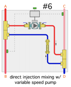 When applied as shown in Figure 2 (assembly #6), variable speed injection mixing can provide setpoint or outdoor reset control functions as well as anti-condensation protection.
The path ahead for variable speed injection mixing is unclear because most currently available controllers for this mixing method are designed for use with permanent split capacitor or shaded pole motors, whereas the circulator world is quickly transitioning to ECM-based motor technology.
Dig Deeper
This article provides an overview of common mixing techniques.
Readers are encouraged to dig into the details and create systems that provide the “right mix” for years to come. <>
 John Siegenthaler, P.E., has designed hydronic systems for over 40 years and has written Modern Hydronic Heating (4th Edition). Visit hydronicpros.com.
