When One Isn’t Enough
March 12, 2024 | By John Siegenthaler
Details for piping multiple hydronic heat pumps.
Multiple boiler systems have been used for decades. They allow full heating capacity to be delivered when necessary, while also retaining high efficiency under partial load conditions compared to a single large boiler.
They also increase the resiliency of the overall heating plant. If one boiler is down for service at least one other boiler is likely ready to supply at least partial capacity.
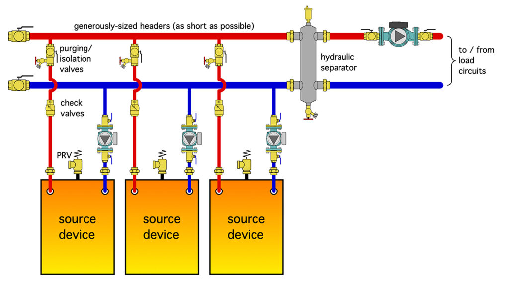
All the benefits of multiple boiler systems also apply to multiple heat pump systems. If the set up is configured to supply heating-only, or cooling-only, the generic system piping is identical to that of boilers, as shown in Figure 1 (above).
Each “source device”, be it a boiler or heat pump, is piped in parallel with the others. Each has its own circulator that operates only when that source device is on. Each source device branch contains a check valve, purging valve and at least one means of isolating the source device from the remainder of the system if it has to be removed or replaced.
The headers that supply and collect flow from the source devices should be short and generously sized (e.g., max flow velocity of two feet per second).
They lead back to a hydraulic separator that isolates the pressure dynamics of the source device circulators from that of the load circulator. The hydraulic separator also provides air and dirt separation.
It’s also possible to pipe a multiple boiler, or multiple heat pump system, using a single variable- speed pressure-regulated circulator along with motorized ball valves on each source, as shown in Figure 2 (below).
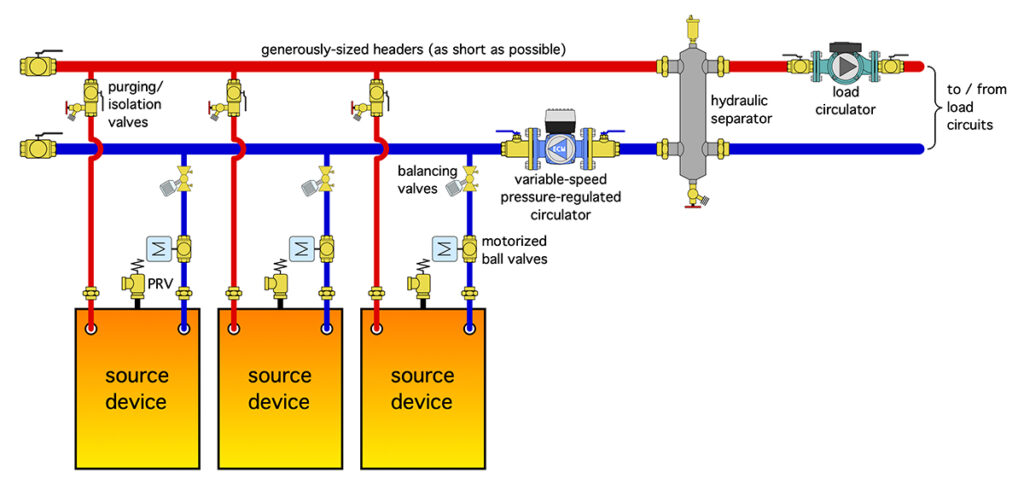
Figure 2. Multiple heat sources using a single variable-speed pressure-regulated circulator and motorized ball valves.
The variable-speed pressure-regulated circulator is set for constant differential pressure mode. It automatically adjusts speed up or down as one or more of the motorized ball valves opens or closes.
In theory, the number of source devices could vary from two up to whatever is needed to meet the design load capacity. However, there are diminishing returns on incremental gains in plant efficiency versus the added cost for piping, as well as space in a mechanical room tends to lead to a “practical” limit of four source devices.
Several manufactures now offer “modular” heat pump products that reduce the external piping requirements. In some cases the header segments are built into each heat pump.
Simultaneity
Many commercial buildings, as well as some large custom homes, can require simultaneous heating and cooling. A common scenario is when the perimeter areas require heating while the “core” areas (e.g., those without exposed exterior surfaces) require cooling due to internal heat gains. Another scenario is when the building contains large glass areas that receive solar gains on sunny winter days.
There are several ways to design HVAC systems that provide simultaneous heating and cooling. They include variable refrigerant flow (VRF), variable air volume (VAV), four-pipe hydronic systems supplying air handlers or fan-coils, and water loop heat pumps.
Monobloc air-to-water and water-to-water heat pumps are another option for applications requiring simultaneous heating and cooling. Systems can be designed that allow any heat pump to operate independently in either heating or cooling mode.
In addition to space heating and cooling, such systems can be configured to heat (or pre-heat) domestic water or add heat to a pool through a heat exchanger. The piping configuration for such a system, based on monobloc air-to-water heat pumps, is shown in Figure 3 (below).
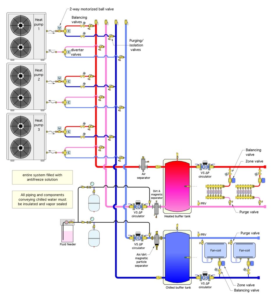
Figure 3. A multiple heat pump set up for simultaneous space heating and cooling.
This design use four risers, two for heated water supply and return, and two for chilled water supply and return. Although shown vertical in Figure 3, these risers can be in any orientation that suits placement of the heat pumps.
Flow in the risers is handled by a single variable-speed circulator set for constant or proportional differential pressure regulation, depending on the length and size of the risers.
If the risers are relatively short and generously sized for a maximum flow velocity of 2 ft/sec., the circulator can be set for constant differential pressure control.
If the risers are long, and represent a significant part of the head loss through the heat pump assembly, proportional differential pressure control can be used.
In either case, the circulator automatically adjusts speed and flow rate as individual heat pumps turn on and off.
Each heat pump uses a pair of three-way diverter valves and a single two-way ball valve. The latter only opens when its associated heat pump is running. It ensures that there is no possible “short-circuiting” through inactive heat pumps.
Without this two-way valve the flow path through the heat pump remains open to either the heating or cooling risers when the heat pump shuts off. This creates a flow path, but with no heating or cooling input.
For example, if the heat pump shuts off in heating mode, the two three-way diverter valves remain in the heating position, which allows cooler heating water to flow through an inactive heat pump and then on to the hot water riser. This “thermally dilutes” the temperature in the hot water riser.
Each set of risers leads to a buffer tank, one for heated water and the other for chilled water. For the system shown in Figure 3, heated water from the buffer tank is routed to multiple radiant panel manifold stations, and chilled water is routed to multiple fan-coil units.
These emitters are only examples. The heated water could also go to panel radiators, chilled beams, or even satellite air handlers.
Flow on the load side of the buffer tanks is also handled by variable-speed circulators set for proportional differential pressure mode. Each crossover between the distribution supply and return pipes has a zone valve that opens when that crossover is active and closes at all other times.
In addition to thermal buffering, each buffer tank provides hydraulic separation between the circulator supplying the heat pumps, and the load circulator.
The two three-way diverter valves and single two-way valves shown for each heat pump in Figure 3 could be replaced by four two-way valves. However, this likely adds to piping cost and also creates more points of potential failure.
The controls for this system would monitor the temperature of both buffer tanks. Since there is a limit to both heating and cooling capacity, and since any heat pump can only operate in one mode at a time, the control logic must prioritize heating over cooling, or vice versa.
In winter it’s likely that the priority would be heating, and thus operating the heat pumps to maintain the temperature in the heated buffer tank based on some setpoint or outdoor reset schedule.
Cooling operation might only be allowed when the temperature in the heated buffer tank is within some differential of the target temperature.
During summer the priority would likely switch to cooling. The only heating load might be domestic water heating (if present), or early morning warming of select spaces using low mass heat emitters.
Variations
Air-to-water heat pumps with variable speed “inverter” compressors are becoming more common. It’s possible to leverage their modulating capacity control with staging to improve the load tracking ability of a plant. Doing so is analogous to how modulation and staging are now commonly combined with boilers.
A heat pump with a variable speed compressor can reduce its capacity to about one-third of its rated output. If two were combined the overall turn-down ratio would be approximately 6:1.
This range of capacity modulation can eliminate the need for buffer tanks. Hydraulic separators would take their place, as shown below in Figure 4.
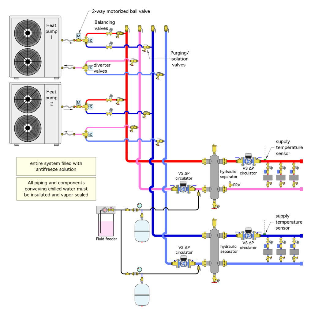
Figure 4. Heat pumps with inverter compressors could eliminate the need for buffer tanks.
System controls would monitor the supply on both the heating and cooling distribution system and operate the heat pumps based on load priority of the desired “target” supply water temperatures.
Another option is based on two three-way diverter valves at each heat pump, but those valves must have three position settings: one to connect to the heating risers; another for connecting to the cooling risers; and a third that blocks flow through the heat pump when it’s off. Figure 5 (below) shows all three modes for the valve.
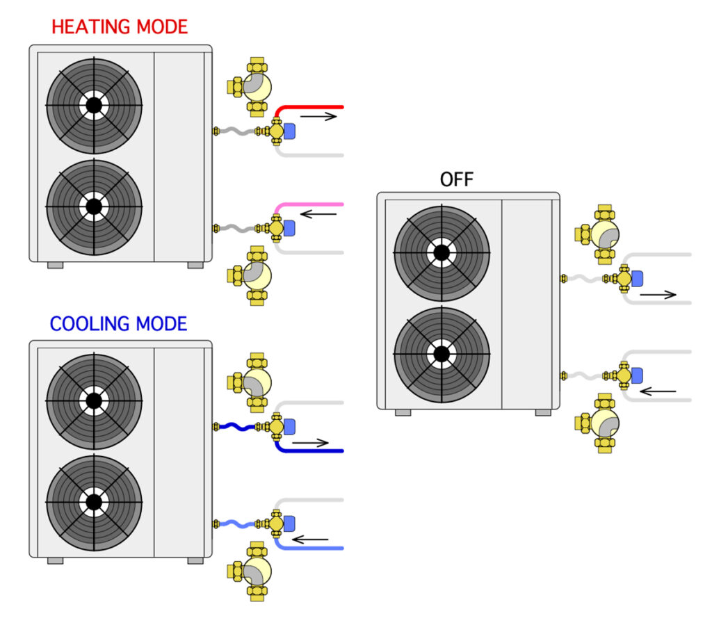
This approach eliminates the need for a two-way motorized ball valve to block flow through a heat pump that is off.
Most three-way ball valves could provide the necessary positions. What’s missing (at least from my inquiries) is a three-position actuator. If anyone knows of a source I’m all ears.
The piping concepts shown can also be applied to water-to-water heat pumps sourced from a common earth loop. It would also be possible to combine heat pumps with one or more boilers. The boiler(s) would obviously only connect to the heating risers.
The market for heat pumps as alternatives to fossil fuel boilers is growing rapidly. Designers need to have concepts for deploying multiple heat pumps ready to roll. <>