
Expansion tank dos and don’ts
May 24, 2019 | By John Siegenthaler
When water is heated the space required for each molecule increases. Any attempt to prevent this expansion will be met by tremendous forces. If a strong metal container is completely filled with liquid water and sealed from the atmosphere it will experience a rapid increase in pressure as the water is heated. If this pressure is allowed to build that container will eventually burst, in some cases violently.
To prevent such a result, closed-loop hydronic systems are equipped with an expansion tank. The tank provides a “cushion” of air–a highly compressible fluid–against which the expanding water can push without creating large pressure increases in the system. Think of the air in the tank as a spring. As the system’s water expands this “spring” gets compressed. When the water cools and contracts, the “spring” returns to its original condition.
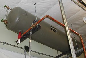
Figure 1 Standard expansion tank
Older systems often used “standard “expansion tanks, in which air and water are in direct contact. This type of expansion tank is typically suspended from the ceiling of a mechanical room. This allows air released from the system’s initial charge of water to move upward into the tank. An example of such a tank is shown in Figure 1.
Although functional, standard expansion tanks are significantly larger than modern diaphragm-type or bladder-type expansion tanks. As such they are more expensive, heavier and require more mounting space. If not equipped with the proper fittings they can also fill with water over time and become “water-logged.” They are seldom used in modern hydronic systems, especially in residential or light commercial building applications.
SEPARATING AIR AND WATER
Today, the most commonly-specified expansion tank for hydronic heating or cooling systems uses a highly flexible butyl rubber or EPDM diaphragm to completely separate the air and water inside the tank. This diaphragm conforms to the internal steel surface of the tank when the air side is pressurized, as shown in Figure 2.
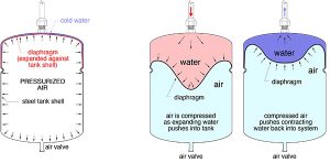
Figure 2 EPDM diaphragm separates air and water in the tank
When the system’s water is heated and expands into the tank, the diaphragm deforms and moves toward the captive air chamber. The air pressure in the tank increases and so does the water pressure in the system. However, if the tank is properly sized, the increase in system pressure is not enough to cause the pressure relief valve to open, even when all the water in the system reaches its maximum temperature.
Diaphragm expansion tanks can be sized using charts or software. A detailed procedure for sizing diaphragm-type expansion tanks is given in reference 1, as well as several other industry publications. The key concepts are:
1. Pressurizing the air side of the tank to equal the static pressure of the water at the expansion tank location and before adding water to the system. This prevents cold water from partially compressing the air in the tank. The diaphragm only begins to compress when the water temperature rises.
2. Size the tank so that the pressure at the system’s pressure relief valve is 5 psi below that valves rated opening pressure when all fluid in the system is at maximum anticipated temperature. The five psi margin prevents the relief valve from “dribbling” as the pressure approaches its rated opening pressure.
Even when an expansion tank is properly sized, installation details can make or break its ability to function as intended and to provide many years of service.
THE DOs
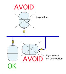
Figure 4 Mounting diaphragm type expansion tank
1. Do Pump Away: A detail that was once understood and respected in the hydronics industry, but slowly faded in priority against other packaging or installation “conveniences,” is to connect the expansion tank into a hydronic piping circuit near the inlet of the circulator. Doing so minimizes the pressure drop between the point where the tank connects to the circuit, that is the point where there is no change in pressure when the circulator turns on, and the circulator’s inlet. This allows the differential pressure created by the circulator to be added to the static pressure in the system. Increased system pressure helps protect the circulator from cavitation and often allows for quieter operation. It also enhances the ability of air vents to eject air from the system. Figure 3 shows several acceptable placements of the tank.
2. Do mount tank vertically with connection at top: It is also best to install diaphragm type expansion tanks vertically with the piping connection at the top. This reduces stress on the tank’s connection relative to horizontal mounting. It also allows prevents air in the piping from getting trapped on the water side of the expansion tank when the system is first filled. Figure 4 illustrates the differences.
3. Do check the air pressure: It is important to verify the air side pressure in the tank equals the static pressure that will be present at the tank’s connection when the system is filled with cold fluid. Most manufacturers state their tanks are pre-charged to 12 psi. Do not assume this is always true or correct. Twelve psi is appropriate for systems where the top of the piping is about 16 feet above the inlet of the expansion tank (assuming that 5 psi static pressure is desired at the very top of the system to allow air vents to function properly). Taller piping systems require higher air pressures to prevent partial compression of the diaphragm before the fluid is heated. Calculate the static pressure at the tank inlet using formula 1.
Formula 1:
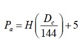
Where:
Pa = correct air side pressure (psi)
H = distance from expansion tank connection to top of piping circuit (feet)
Dc = density of the “cold” fluid in the system when it is at approximately 60F (lb/ft3)
5 = 5 psi static pressure desired at top of system for air vent operation
144 = units conversion constant
For example: if the top of the piping circuit was 25 feet above the expansion tank connection and assuming the system is filled with water, the correct air side pressure in the tank would be:
Get a low-pressure tire gauge with a scale of 0-30 psi and a bicycle pump or small air compressor. Use them to set the calculated air side pressure before filling the system with fluid.
4. Do Plan ahead: The life of an expansion tank depends on system operating temperature, pressure, fluid chemistry and oxygen content. Some tanks fail when a leak develops in the diaphragm. This usually causes the tank to fill with fluid and become “water logged.” You can check for this by pressing in the stem of the Schrader valve. If a stream of liquid comes out the tank is toast. Tanks can also develop leaks in their thin steel shell. The only option is a new tank. This is when you will appreciate having a ball valve that can isolate the tank from the remainder of the system. Without this valve you might have to drain several gallons of fluid from the system just to unscrew the failed tank and screw in a new one.
5. Do consider oversizing: The typical calculations for sizing a diaphragm expansion tank determine the minimum tank volume. Using a larger tank, although likely more expensive, is fine. Doing so reduces changes in system pressure as the fluid temperature varies.
6. Do plan for lowest fluid temperatures: In most hydronic heating systems expansion tank size and air side pressurization is based the assumption that the cold fluid used to fill the system in the temperature range of 45F to 60F. That is fine. However, when an expansion tank is used in a solar collector circuit, or a snowmelting system, the antifreeze solution will, at times, be much colder, perhaps even below 0F. If the tank’s diaphragm is fully expanded against the steel shell at a fluid temperature of perhaps 45F, any further cooling of the fluid could cause negative pressure in the system and possible inflow of air from a float-type vent. Reference 2 below explains how to correct for this possibility. The concept is to add sufficient fluid to the tank during loop pressurization so that the diaphragm is not completely expanded against the inside of the tank until all fluid in the system is at the lowest possible temperature.
7. Do adjust for antifreeze solutions: Solutions of propylene or ethylene glycol have higher coefficients of expansion compared to water. The higher the concentration of antifreeze the greater the expansion volume required. The increase in volume for water heated from 60F to 180F is about three per cent. The increase in volume for a 50 per cent solution of propylene glycol heated from 60F to 180F is about 4.5 per cent. This should be accounted for when sizing tanks for systems such as snowmelting, solar thermal, or other applications where glycol-based antifreeze solutions are used. Again, the methods in Reference 1 can adjust for this.
THE DONT’S
As usual, a list of all of the “don’ts” would inherently include the opposite of all the “dos.” Still, there are a few more “don’ts” that stand out.
1. Do not combine steel and oxygen: Do not use a standard expansion tank with a carbon steel shell in any type of open loop application, such as a system that uses potable water to carry heat to hydronic heat emitters, which is a bad idea for a number of other reasons. The elevated dissolved oxygen content of the water in an open loop system, relative to that in a closed-loop system, will accelerate corrosion of the thin carbon steel shell of the tank. This limitation also applies to closed-loop systems using non-barrier PEX tubing or other materials that may allow oxygen diffusion in the system. Expansion tanks with internal polymer linings should be used in any application where higher levels of dissolved oxygen could be present.
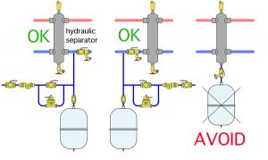
Figure 5 Expansion tank installed near hydraulic separator
2. Do not fill it with dirt: Do not install expansion tanks directly below hydraulic separators. Doing so allows dirt collected at the bottom of the separator to drop into the expansion tank. Over time this could lead to failure of the diaphragm. If the tank needs to be near a hydraulic separator it is best to mount it from a tee in either pipe connecting to the lower sidewall connections on the separator, as shown in Figure 5.
3. Do not Overheat It: Whenever possible, avoid locating expansion tanks in close proximity to very hot water. When the tank’s shell is heated by heat migration (conduction and convection) the pressure of the air in the tank increases. All other factors being equal, this increases system pressure relative to a situation where the tank shell is cooler. It may lead to leakage of the pressure relief valve. It is fine to locate the tank several feet away from where the tube from the tank connects to the system. Keep the tank lower than this connection point to reduce heat migration by convection.
4. Do not create multiple connection points: It is fine to use two or more expansion tanks with a combined volume of a single larger tank. However, those tanks should connect to a common pipe, which has a single connection point in the system. Avoid connecting multiple tanks to different parts of the same piping. This can cause unexpected pressure variations depending on where the circulator(s) are located relative to the tanks.
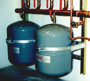
Figure 6 Strapping system secures tank shell
5. Do not leave it vulnerable to impact: Small expansion tank that hang from ½ in. top connections can be easily bent by accidental impact, such as someone standing up from a bent over position and bumping the tank. Ask me how I know this… If the tank must be mounted in a vulnerable location use a strapping system to secure the shell to a solid surface, as shown in Figure 6. Some expansion tank manufacturers offer strapping kits or other hardware to properly support the tank shell.
In addition to the strapping notice both tanks have isolating balls and sufficient room for accessing the Schrader air valve at bottom. Both tanks are connected in parallel to a common pipe, allowing for a single connection point to the circuit.
6. Do not assume compatibility: Be sure the expansion tank you select is compatible with the fluid used in the system. Combined butyl/EPDM or all-EPDM diaphragms are generally compatible with glycol solutions and the methanol or ethanol solutions sometimes used in geothermal ground loops. However, different tank suppliers use different materials and have different temperature limits on those materials. It is always best to get approval from the tank manufacturer on fluid compatibility.
Expansion tanks perform a simple but very necessary function. Follow these tips to make and keep them functioning as intended. <>
FOR MORE CONTENT LIKE THIS VISIT: 10 Details for Expansion Tanks
John Siegenthaler, P.E., is a mechanical engineer with more than 40 years experience in designing modern hydronic heating systems. Siegenthaler l is author of Modern Hydronic Heating & Cooling (fourth edition) and Heating with Renewable Energy (see www.hydronicpros.com for more information).
References
1. Modern Hydronic Heating, 3rd Ed., John Siegenthaler, Cengage Publishing 2012, ISBN -13: 978-1-4283-3515-8
2. Heating with Renewable Energy, John Siegenthaler, Cengage Publishing 2017, ISBN -13: 978-1-2850-7560-0

