
Taking out the Trash
January 2, 2024 | By Dave Demma
Overcoming the obstacles to delivering a trouble-free refrigeration system start up.
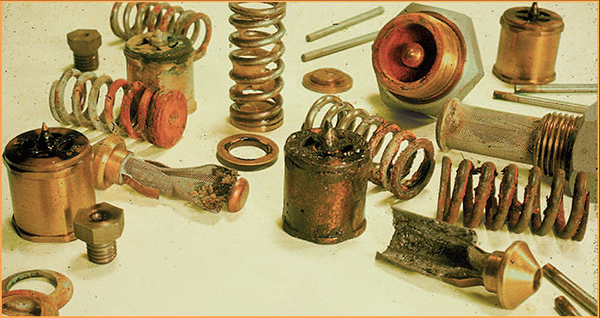
Figure 1. TEVs with contamination issues which were returned for warranty credit.
The long-term health of your air conditioning or refrigeration system is dependent on four things: proper design, quality installation, equipment commissioning, and ongoing preventative maintenance.
Assuming the system design engineer has done his job correctly, the burden of delivering a trouble-free system falls upon the installing contractor. Forever has this been the case.
So, with a quality installation contractor on the job, there is one maxim that should be emblazoned in every technician’s mind: system cleanliness is vital to the health of the system.
I went over the steps to cleanliness a decade ago on these pages, but it’s now time for a refresher.
This process of system cleanliness starts with taking care to ensure that no foreign particulate matter enters the system piping during the installation.
The presence of particulate matter, ‘trash’, in the system can have any of the following three negative impacts:
1. Control valve failure: trash can restrict refrigerant flow by plugging up valve ports, orifices, small passageways in pilot assemblies on pilot operated valves, and valve piston bores. This will respectively restrict refrigerant flow, restrict the ability of a pilot assembly to pressurize and/or vent the piston chamber (necessary in pilot operated valves for piston modulation), and cause piston stickage due to the buildup of contaminant between the piston and piston bore.
Many “alleged” valve failures are nothing more than flow restrictions due to trash; restricted pilot ports in pilot operated EPR valves, solenoid valves, and discharge bypass valves preventing proper piston movement, or restricted main piston/port in TEVs preventing refrigerant flow (see Figure 1 above).
2. Plugged filters-driers, filters, and strainers: a plugged liquid line filter-drier will cause excessive pressure drop to the liquid refrigerant flowing through it. Where there is little or no liquid subcooling present, refrigerant vapourization (flashing) will occur, reducing the supply of liquid refrigerant to the TEVs. The result is a loss in TEV capacity, which in turn results in a loss of heat transfer capacity.
In extreme situations, particularly on systems without receivers, the plugged liquid filter-drier may result in increased head pressure.
A plugged suction filter will lower the pressure at the compressor inlet, increasing the compression ratio, and decreasing the compressor capacity.
In mild cases additional compressor run time will be required to achieve the design temperature in the refrigerated space. In extreme cases the compressor capacity reduction will prevent the design temperature from being met.
Additionally, excessive suction filter pressure drop will significantly reduce the suction vapour velocity, preventing the oil from returning with the refrigerant to the compressor.
Some larger model compressors may come equipped with an inlet strainer, however, the screen is typically course. This is by design. Their purpose is simply to prevent larger particles from entering the compressor. Too fine of a strainer would plug up easily, resulting in an unusually high pressure drop between the compressor inlet and the cylinders.
A plugged compressor inlet strainer will yield the same set of problems as a plugged suction filter (see Figure 2).
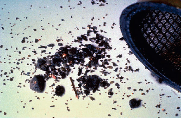
Figure 2. Compressor inlet strainer with installation trash (copper oxide, sil-phos, copper chips).
Multi-compressor systems using an oil management system (oil separator and individual compressor oil level controls) will normally have an oil filter in the oil supply line to the oil level controls. If the oil filter becomes plugged, the oil level in each compressor crankcase will eventually drop to an unsafe level, causing the oil failure control to lock the compressor off.
3. Compressor damage/failure: smaller trash particles will travel through the compressor inlet strainer (if indeed the compressor has one) and enter the crankcase. Once there, the trash particles will travel through the compressor lubrication system with the oil, acting as an abrasive on bearings, bearing journals, piston rings, and piston cylinders.
In extreme cases the oil sump inlet strainer or the compressor’s oil passageways can become plugged, resulting in a complete loss of lubrication. While it may take some time, this will lead to a failed compressor.
Eliminating the Trash
The first step in eliminating installation related trash particles is to implement a practice of flowing nitrogen through the copper piping during the brazing process. This will prevent the formation of copper oxide on the interior surface of the piping at the braze joint locations.
Secondly, good practices and procedures should be used to prevent other forms of particulate matter from entering the piping (copper chips, brazing rod, sand, dirt, etc.). One often overlooked form of contamination comes from excessive amounts of flux being applied to dissimilar metal braze joints; this should be avoided.
Even with the best of intentions every system will have some residual trash particles remaining after the installation. This is why liquid line filter-driers are standard issue on all factory-built equipment.
As the name implies, part of the filter-drier’s function is to filter out destructive trash particles from the refrigerant and oil in the system. It is important to remove these trash particles before they can pass through the compressor.
At startup, you have one shot to remove trash particles located between the compressor outlet and the liquid line filter-drier inlet before they can travel to the compressor.
Given the importance in removing these trash particles on a first pass basis, a lower micron rated filter would be preferred for start-up situations (see Figure 3).
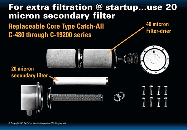
Figure 3. Secondary filter for replaceable shell liquid filter drier is preferred for start-up. (source: Parker Hannifan Corp.)
Any trash particles located between the liquid line filter-drier outlet and the compressor inlet will have to pass through the compressor before the liquid filter-drier will have the opportunity to remove them. This is the “why” for using a suction line filter; it is undesirable to allow any trash particles to flow through the compressor before arriving at the inlet of the liquid filter-drier.
Smaller systems with close coupled piping runs, especially those built in the controlled environment of a manufacturing plant, may not require the use of a suction filter; the possibility of any measurable amount of trash between the liquid filter-drier outlet and the compressor inlet will be minimal.
Larger systems with remote compressors and lengthy runs of field installed piping are a much different story; particularly supermarkets and warehouses where the total length of piping may be measured in miles instead of feet.
In applications such as this it is almost certain that significant amounts of trash will occupy the lengthy piping runs between the liquid filter-drier outlet and the compressor inlet. It is therefore essential to install a suction filter (or as required…suction filters) on these systems. Figure 4 shows examples of typical suction filters.
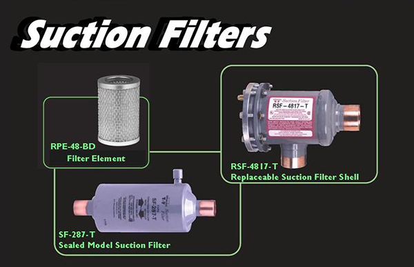
Figure 4. Examples of sealed model and replaceable shell suction filters.
Suction filters and liquid filter-driers are the final check and balance to ensure that any residual contaminants remaining from the installation process are removed. They should be installed immediately prior to system evacuation.
Suction filters and liquid filter-driers should not be viewed as a substitute for good installation practices, but rather as extra insurance.
System Evacuation
It should also be noted that the presence of moisture and/or air in the system will have devastating effects on long term system health. After the piping and component installation is complete, the system should be pressurized with dry nitrogen, or a mixture of dry nitrogen and a trace amount of refrigerant (following environmental guidelines) so a complete leak check can be performed.
Any identified leaks should be repaired and the system re-pressurized. If no reduction in pressure is experienced over a 12-hour period, the system can be considered leak free. (Note: equipment and component manufacturer’s pressurization guidelines should be followed).
Once leak free status is obtained the system should be evacuated.
“Why is it necessary for a refrigeration system (new or existing) to be evacuated?” you ask.
Because the piping and components have been open and exposed to the atmosphere during the installation process. Our earth’s atmosphere consists of 78% nitrogen, 21% oxygen, an assortment of rare gasses and man-made pollutants, and some amount of water vapour.
Here are the potential problems in forgoing system evacuation:
1. Non-condensable gasses: The function of the condenser is to transfer enough heat from the superheated discharge vapour to yield a saturated/subcooled liquid at its outlet. Any reduction in condenser capacity will have a negative impact on the condenser’s ability to perform this function.
Oxygen and nitrogen are both non-condensable at the temperatures normally experienced in the typical refrigeration condenser. If not removed from the system, they will accumulate in the condenser, taking up valuable space that should be reserved for refrigerant vapour to go through the change of state process.
The subsequent reduction in condenser capacity will result in a higher condensing pressure (reduction in compressor capacity and higher electrical consumption) and a higher discharge temperature (the potential for the refrigerant and/or oil to suffer chemical breakdown at an accelerated rate.
2. Oxygen: Studies have shown that the rate of chemical breakdown increases when air (oxygen) is present in the refrigeration system. Its greatest threat is the potential to oxidize the compressor oil, which will occur at accelerated rates as the temperature increases (the rate of chemical reaction doubles for every 18F increase in temperature).
Oil that has suffered a chemical breakdown turns into a sludge and becomes acidic. Sludge may plug up control valves and affect proper lubrication of the compressor’s rings and bearings. Acid formation puts the insulation on hermetic compressor motor windings at risk of deterioration. Once the acid has eroded the winding insulation, shorting can occur, resulting in a failed motor.
3. Moisture: Studies have proven that the rate of chemical breakdown (the formation of acids and oil breakdown) is accelerated if moisture is present in the system. The hydrogen in the water molecule can combine with the chlorine and/or fluorine molecules in the refrigerant to form HCl (Hydrochloric acid) or HFl (Hydrofluoric acid).
Moisture can also cause corrosion, and this will accelerate the process of copper plating (where molecules of copper from the piping become displaced to heat bearing surfaces in the compressor, such as bearings and pistons).
In addition: every refrigerant has a water solubility curve, which will show the maximum water content (in PPM) that the refrigerant can hold in solution at a given temperature.
As the temperature is reduced, the ability of the refrigerant to hold water in solution is also reduced, and when this happens the the excess water comes out of the solution and exists as free water. In an application where the refrigerant temperature is below 32F/0C the free water will freeze, rendering the TEV inoperable, negatively affecting its ability to maintain its superheat set-point.
Thus, this is why evacuation is essential.
Stay tuned, because in my next column for HPAC I will walk us through the evacuation process. <>
 Dave Demma holds a degree in refrigeration engineering and worked as a journeyman refrigeration technician before moving into the manufacturing sector where he regularly trains contractor and engineering groups. He can be reached at ddemma@uri.com.
