
Introduction to refrigeration defrost methods-Part II
March 19, 2017 | By Dave Demma
Refrigeration systems operating with saturated suction temperatures below freezing will eventually experience an accumulation of frost on the evaporator tubes and fins. The frost serves as an insulator between the heat to be transferred from the space and the refrigerant, resulting in a reduction in evaporator efficiency. Certain techniques must be employed to periodically remove this frost from the coil surface.
Refrigeration defrost methods can include, but are not limited to off cycle or air defrost and electric, which were addressed in Part I in HPAC February 2017, and gas, which will be discussed in this article. Modifications to these basic defrost schemes add yet another layer of complexity for field service personnel. When properly setup, all methods will achieve the same desired result of melting the frost accumulation. If the defrost cycle is not set up correctly, the resulting incomplete defrosts (and reduction in evaporator efficiency) can cause higher than desired temperature in the refrigerated space, refrigerant floodback or oil logging issues.
GAS DEFROST
Gas defrost uses the system’s internal energy to defrost the evaporator, utilizing the naturally occurring high temperature discharge vapour to add the necessary heat required to accomplish the defrost cycle. Through the years, refrigeration systems have employed several different methods for introducing the hot gas to the evaporator. These include: reverse cycle, three pipe and reverse flow. Each of these methods has been perfected further as different manufacturers have refined the operation to suit their needs.
Reverse Cycle: When thinking of a reverse cycle style of defrost a heat pump often comes to mind. During the normal refrigeration cycle, the system acts just like any other DX system where the condenser provides the liquid refrigerant that will feed the system TEVs. The TEVs meter refrigerant into the evaporator as required based on the load, resulting in a refrigeration effect. On systems where the evaporator saturated suction temperature is below 32F, the formation of frost will occur on the evaporator fins and tubes. This method requires a four-way reversing valve, which allows the system refrigerant flow to be reversed at the initialization of the defrost cycle. The compressor discharge vapour is now directed backwards through the evaporator, condensing the high pressure vapour into a liquid and melting the frost buildup in the process. The newly created liquid refrigerant must now be passed through an expansion device and allowed to vapourize as it passes backwards through the condenser before returning as a low pressure vapour to the compressor suction.
This method results in a faster defrost, but several design and operation precautions must be addressed. First, the system will require two expansion valves and a series of check valves to expand the liquid refrigerant in both modes successfully. On systems utilizing a refrigerant distributor, the nozzle orifice will not be of sufficient size to allow the defrost gas to flow through it without experiencing excessive pressure drop. A side outlet distributor (or standard distributor with an auxiliary side connector) must be used to allow the defrost gas to flow around the distributor nozzle. On close coupled systems with a single evaporator and no liquid receiver, a single expansion device (designed to operate for reverse flow operation) may be used to feed both the indoor and outdoor coils. In this case either a balanced port or electric expansion valve is recommended and it should be located in the common liquid line between the evaporator and condenser. Additionally, if a liquid pump down solenoid is used, it must also be designed for reverse flow operation. A special bi-flow filter drier is necessary in the common liquid line. If a suction filter is used, or if a suction filter-drier has been added during a clean-up procedure, it will need to be installed in the suction line between the reversing valve and compressor.
Three Pipe: This method of defrost is named for the addition of a distinct third pipe running between the compressor rack and the evaporator(s), that is the defrost gas supply pipe. Hot gas is taken from the compressor discharge and introduced to the inlet of the evaporator, but downstream of the TEV. Once again, we have refrigerant condensation of the defrost gas. As it flows forward through the evaporator its heat energy is transferred to the frost accumulation on the evaporator fins and tubes. This liquid has nowhere else to go other than back towards the compressor, so an adequately sized accumulator is usually required.
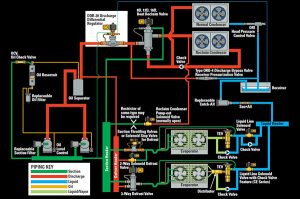
Gas discharge with a discharge differential valve
One of the drawbacks with single evaporator systems utilizing hot gas defrost is the elimination of any meaningful load on the compressor during the defrost cycle. With the evaporator receiving hot gas at its inlet and acting like a condenser in the process of melting the accumulated frost, the refrigeration cycle cannot continue for long without a refrigeration load. So, the defrost duration needs to be extremely short on single evaporator systems, or some method of adding false load to the compressor must be utilized (more on this momentarily). With multiple evaporators piped to a common suction line, this can be achieved by limiting the number of circuits in defrost at any given time – typically no more than 25 per cent. This will allow sufficient compressor load to generate enough high temperature discharge vapour to accomplish the defrost cycle.
Kramer Thermobank: Another unique gas defrost solution in the industry was introduced as the Kramer Thermobank system. Its design successfully solved the problem of limited availability of high temperature discharge vapour available for defrosting single evaporator systems. During the normal refrigeration cycle the discharge line is piped through a heat exchanger containing a static volume of glycol. This heat exchanger is appropriately called the Thermobank. Defrost is carried out in the typical three pipe fashion, but a series of solenoid valves allow the liquid generated in the evaporator to pass through the “Thermobank” before returning to the compressor suction. This heat source provides the necessary load to cause the liquid to undergo a change of state (into a vapour), allowing the refrigeration cycle to continue. As a side benefit, the process of warming the Thermobank serves to reduce the compressor discharge vapour temperature.
Reverse Flow Defrost – Hot Gas: Since piping runs are relatively long in supermarkets, gas defrost generally takes the form of reverse flow defrost. This method utilizes the existing circuit suction line to introduce the flow of the discharge vapour in a reverse flow direction through the evaporator system. Discharge vapour from the common discharge line is piped to a defrost header, which then supplies the defrost vapour to each individual evaporator circuit through a defrost solenoid valve.
To accomplish reverse flow a suction line regulator must be installed upstream of the common suction header and electrically closed during the defrost cycle, otherwise the discharge vapour would take the path of least resistance and flow to the compressor’s suction header. The suction regulator may be any of the following: suction solenoid valve, Evaporator Pressure Regulator (EPR), or Electric Evaporator Pressure Regulator (EEPR). The high-pressure gas flows in reverse through the lower pressure suction piping and evaporator and eventually exits to the liquid header via check valves around the TEV and liquid line solenoid valve.
Reverse flow of refrigerant from the discharge line backwards through the evaporator to the liquid header cannot be guaranteed without some flow manipulation. Refrigerant always flows from high pressure to low pressure. So, the discharge vapour supplied to the evaporator for defrosting purposes must always be at a higher pressure than the liquid header, even though they are both on the “high side” of the system. Granted, there is a natural pressure difference between the discharge header and the liquid header due to normal frictional piping losses, but this will not be a sufficient pressure differential to achieve the necessary flow of discharge vapour for a timely and adequate defrost. Therefore, a valve capable of providing a differential in pressure must be installed somewhere between the defrost header and the liquid header.
This valve is known as the defrost differential valve. For a traditional hot gas defrost system, the defrost differential valve is placed in either the discharge line (downstream from the oil separator) or in the liquid line (upstream of the liquid header).
Note that in older systems, pressure differential in the liquid line was accomplished by using a differential check valve piped in parallel with the main liquid line solenoid valve. During the defrost cycle, the main liquid line solenoid valve would be de-energized and the refrigerant would then flow through the differential check valve. The pre-set rating of the differential check valve would determine the pressure differential available for defrosting.
As the name implies, defrost differential valves are set to maintain a differential between the supply of discharge vapour for defrost and the liquid header. In the case of the discharge differential valve, the inlet (discharge) is set to approximately 20 psi higher than where the pilot line is piped (the receiver). Since the valve insures the discharge vapour is 20 psi higher than the receiver pressure, the gas now has enough pressure differential available to move backwards through the evaporator. The liquid differential regulator works in much the same way, except it is piped in the liquid line, upstream of the liquid header and maintains a differential across its inlet and outlet. Both of the designs incorporate an electric open feature that allows the valve to go wide open for minimum pressure drop during periods when no evaporator systems are in defrost.
When the defrost timer initiates a defrost cycle, several things happen simultaneously. The suction line regulator is closed by de-energizing its pilot solenoid coil, preventing any high-pressure vapour from entering the suction header. The liquid solenoid valve is de-energized and the circuit defrost solenoid valve is energized, opening and supplying discharge vapour to the evaporator inlet, which initiates defrosting. The discharge differential valve is also electrically switched to its differential mode, providing the necessary pressure differential to ensure a timely and complete defrost. The entering discharge vapour condenses into a liquid as its heat content is transferred to the evaporator tubes and fins, melting the frost accumulation in the process. It is ideal that the newly-formed liquid ends up in the liquid header where it can be used to feed cases still in the refrigeration mode.
System design engineers are always concerned with the “what if” scenario when a system component fails. In regard to the liquid defrost differential valve, there are two schools of thought as to which mode this valve operates in if there is a solenoid valve failure.
Some applications will utilize a differential valve that is in the differential mode when the coil is energized. If a coil failure occurs the system will operate as designed during the refrigeration mode, but will not provide any differential for defrosting purposes. Systems utilizing gas defrost will be unable to maintain adequate temperatures due to the excessive frost buildup on the evaporators and service calls will follow.
Other applications will utilize a differential valve that is in the differential mode when the coil is de-energized. If a coil failure occurs on this valve there would be issues with abnormal pressure drop in the liquid line. Without an adequate amount of subcooling to prevent refrigerant flashing, the entire system will be unable to maintain design temperature conditions, again prompting a service call. If there is adequate subcooling to prevent liquid flashing, this failure may go unnoticed for some time as there will be a constant differential available for whenever any system goes into its defrost cycle.
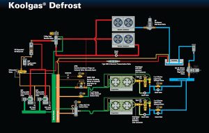
Koolgas defrost with liquid differential valve
Koolgas Defrost: Hussmann offers a patented variation to the standard reverse flow hot gas defrost cycle. In its design the defrost header is supplied with saturated vapour from the top of the receiver, instead of superheated vapour from the discharge line. This “Koolgas” helps minimize the thermal expansion that occurs when subjecting a cold suction line to elevated defrost gas temperatures.
In addition, using saturated vapour will accomplish a quicker defrost cycle than when using superheated discharge vapour. This might go against logical thinking, given that the discharge vapour is considerably higher in temperature than the saturated vapour from the top of the receiver. However, the heat content in Btu/lb of the vapour has to be considered as well. The saturated vapour from the receiver is much denser than the discharge vapour. Its heat content is greater per pound than the less dense discharge vapour. Think of the flame on a match, which burns at somewhere between 600F to 800F versus a gallon of water at 100F. Clearly the match’s flame is much hotter than the water. Due to the water’s mass, its heat content per pound is considerably greater. Likewise, the greater mass of the saturated vapour provides greater heat content to the evaporators’ fixed internal piping volume, resulting in a quicker defrost.
Given that the Koolgas method utilizes saturated vapour from the receiver as the defrost gas, the differential between the defrost gas and the liquid header must now be taken in the liquid line (upstream of the liquid header). This is the only option to ensure that the defrost gas will have a higher pressure than the liquid header.
POTENTIAL ISSUES
The two greatest field struggles with reverse flow gas defrost come with setting the differential valve and determining what percentage of the total system capacity should be in defrost at any given time. First, the differential valve should be set with no systems in defrost, but in differential mode. This may require tricking the system into the differential mode by manually energizing/de-energizing the valve’s coil (or using the energy management system to initiate a defrost cycle) and close the defrost header ball valve to prevent discharge vapour from entering the evaporator system.
As previously stated, approximately 20 psi of pressure difference is needed to guarantee reverse flow. However, additional pressure differential will be needed if the compressors and liquid header are in an elevated machine room above the evaporator systems. In this instance, the defrost gas comes down to the evaporator system as a vapour so no noticeable pressure increase occurs. But, the gas condenses in the evaporator system and returns back to the elevated liquid header as a liquid. For every foot of vertical lift the liquid must travel, it will lose approximately ½ psi, reducing the net pressure differential necessary for proper defrost. Therefore, the technician must add an additional ½ psi of differential for every foot of vertical lift.
For example: the differential valve is set to maintain a 25 psi differential, but the compressor rack is 20 ft. above ground level. This 20 ft. vertical lift will result in a 10 psi pressure loss, effectively reducing the differential to 15 psi. The differential valve will need to be reset to 35 psi differential to accommodate the pressure loss.
Finally, only one evaporator circuit should be defrosted at any given time and that circuit should not be more than 25 per cent of the total system capacity. The head pressure will naturally fall at the start of defrost but will rise as the differential valve begins to throttle while maintaining its differential. When utilizing a liquid differential valve, if too much of the system is in the defrost mode at one time, the valve may lose its ability to maintain a differential pressure.
HERE IS THE PROBLEM
The liquid differential valve is sized to handle the full capacity of refrigerant liquid mass flow at the design condition. During periods when a given system is in the defrost mode, the mass flow requirement through the main liquid line will be reduced in the following ways: any system still in the refrigeration mode operating at load conditions less than the design condition will reduce the demand for liquid mass flow; the liquid refrigerant mass flow requirement for the system in the defrost mode will be zero; and the condensed discharge vapour from the system in defrost flows to the liquid header and supplies other circuits with liquid refrigerant, further reducing the mass flow requirement through the differential valve. This reduction in mass flow through the liquid line (upstream of the liquid header) in effect renders the differential valve temporarily oversized. If severe enough, the differential valve may have difficulty operating in a stable manner, yielding an erratic or low differential pressure across its port.
In summertime conditions it is easy to see that there is plenty of discharge heat available to defrost an entire store. Discharge temperatures will naturally rise with the rise in summertime ambient temperatures. This extra heat content, which would have otherwise been rejected to the outside environment, is now available to facilitate the defrost cycle. Wintertime conditions pose a dilemma for systems using gas defrost. For air cooled units, lower ambient temperatures automatically result in a lower head pressure, lower compression ratio and higher compressor efficiency.
So, it is logical that these systems should be set up to operate with the operating head pressure as low as possible. However, there is a natural opposition between the desire to capture energy savings with lower head pressure, yet still have sufficient heat content available in the defrost vapour for a proper defrost. There is a lower limit to how far the head pressure can be reduced and still maintain sufficient heat content in the defrost vapour for an adequate and timely defrost cycle. This will typically be higher than the minimum allowable head pressure during the refrigeration cycle, particularly if the system does not utilize heat reclaim and employs electric expansion valves (EEVs).
While gas defrost eliminates the expense of defrost heaters, control relays and/or contactors, the required field installed wiring and the monthly electrical expense to power the defrost heaters, it does require that the head pressure be artificially elevated to provide adequate heat content to accomplish the defrost cycle.
It could be argued that a system without a heat reclaim circuit, which also requires elevated head pressure in the lower ambient months to generate sufficient heat in the discharge vapour, and using EEVs, and utilizing electric defrost could reduce winter head pressures even further than the minimum head pressure required for proper gas defrost. This assumes that the compressor is designed accordingly. With this being the case, as the ambient falls there will come a point where the energy savings with gas defrost may be offset by the energy penalty for the required elevated head pressure.
Assuming that it is TEV sizing, not gas defrost requirements, that necessitates head pressure controls; reverse flow gas defrost does not require any additional energy consumption. Unlike a three pipe gas defrost, the liquid generated during a reverse flow defrost actually enters the liquid header and can be used to meet cooling requirements.
So, from an energy standpoint, it does not matter if discharge vapour is used to heat the ambient at the condenser or to melt ice in the evaporator. However, the discharge defrost differential valve will introduce a pressure drop resulting in higher compression ratios and added energy consumption.
It would be an interesting study to compare the energy consumption of a given supermarket utilizing electric defrost versus gas defrost (taking into account the need to maintain a minimum head pressure for adequate defrost) – perhaps as the subject of a future article.
Dave Demma holds a degree in refrigeration engineering and worked as a journeyman refrigeration technician before moving into the manufacturing sector where he regularly trains contractor and engineering groups. He can be reached at ddemma@uri.com. Co-author Bob Schindler is a regional sales manager at KeepRite Refrigeration.

