
Getting it right – part I: Troubleshooting hydronic control systems
February 23, 2018 | By Mike Miller
Control systems are often blamed when hydronic systems are not operating properly. While that may sometimes be the case, always look at what else may be influencing performance. While control systems are not flawless, consider that they are developed in a controlled environment and are built for a specific purpose.
More often than not, if control systems do not perform as needed, the issue is with the installation or programming side of things. There is absolutely nothing that will minimize downtime and troubleshooting more than getting the system installed right the first time. Nothing will ever replace the need for solid training and acquiring an understanding of the product itself, along with the installation side of things in advance of working with the product.
Related: Getting it right — part II
This series will look at five of the most common reasons why control systems issues arise and provide solutions to those issues. You will read about the following in more detail:
- Sensors used
- Controlled device sizing/piping
- Outputs on controllers
- Wiring of sensors, control signals, communication
- Setup of controls (using multiple stand alone controls, controls with schedules)
Sensors used
Depending on the control systems you are working on, any of the following sensors may be used:
- Outdoor sensor
- Indoor sensor
- Pipe sensor
- Air flow sensor
- Humidity sensor
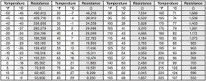
Figure 1. Temperature resistance chart-NTC thermistor, 10kΩ
Some of these may be thermistor type sensors, which operate on a fluctuating resistance scale depending on the temperature those are exposed to. Always consult the manufacturer’s resistance scale, typically found in the installation manual, when checking these sensors. An example of a temperature resistance chart using a very common type NTC thermistor is shown in Figure 1. Please note that not all thermistor type sensors are created equal–they may be operating on a different resistance scale, even the sensor is also labelled 10K. As such, I would not recommend using a third party sensor on anyone’s control, unless you have done your homework and compared the two in detail. Even then, I would always refer back to the control systems manufacturer to get its blessing.
Why would you need this information? You need it in order to troubleshoot sensors that are not accurate. The very first thing I would check is the sensor location and whether or not it is being influenced in any way. The following is a small summary for what could be impacting the sensor’s accuracy from a location perspective.
Pipe sensors
Is the pipe sensor strapped to a pipe that is thermally conductive, such as copper? If yes, that is fine and we will look at how to check a sensor later using Figure 1. If not, it may be strapped to black iron pipe, PVC or anything that is not thermally conductive. If this is the case, then the sensor should be immersed in a sensor’s well. Without that immersion type well, there will be a temperature difference between the fluid that the control system wants to control and what the sensor is reading.
Another important consideration is the strap used to strap sensors to the pipe. Do NOT over tighten this strap; it may expand at a different rate from the sensor as the temperature increases. That in turn could damage the thermistor beat found inside of the sensor itself.
Indoor air and/or outdoor air sensors
In the case of an outdoor sensor, make sure that is installed at a location where it can read nothing but the true outdoor air temperature. It is always recommended that it be located at the north side of a building and under an overhang so that it is protected from the sun and wind. These could falsely affect its temperature reading and therefore provide misleading information to the controller. Unfortunately, I have found outdoor sensors that are affected by sun or wind or even other sources, such as dryer vents and boiler vents.
In case of an indoor air sensor or digital communicating thermostat, make sure that the sensor is not near any other objects emitting heat, such as radiators or air vents. Again, you want to make sure that nothing else can influence its reading other than the true indoor air temperature.
Over the years I have found some indoor air sensors that were affected by draft coming in from behind the thermostat or sensor where the wiring hole in the drywall was too big. The draft from within the framing affected its temperature reading. Make sure that any opening used for wiring in behind the sensor is plugged properly.
If all of the above checks out on the sensor, the first thing to do is to go to the sensor itself and disconnect any connecting wire. Then use an ohm resistance meter and check for the resistance across the two sensor leads and compare it to the resistance chart for this sensor.
If this were the chart in Figure 1 and if the temperature this sensor was exposed to was about 130F, then the resistance should be 3,050 ohms. If it is not, then the sensor may be faulty. Remember that the resistance on this sensor and the temperature it is exposed to should match. If it does match, then reconnect the wiring in between the sensor and the control. Take the same reading with the additional wiring in place to see if something else is off within the wiring itself. If the resistance is equal, then we know the sensor and the wiring are fine.
This could be a very rare case where a controller is actually faulty. If you find a change in resistance consider the reasons discussed below regarding wiring and installation.
Air flow and humidity sensors are very similar in nature and troubleshooting. Most often when I have seen humidity sensors fail or fail to be accurate, dirt or other materials are found to be touching the surface. Most humidity sensors I have worked with in the past use resistance based sensors similar to that of temperature. It is very important that the surfaces be inspected and cleaned periodically. If the readings are off, follow the same troubleshooting as with the temperature sensors explained previously. Check the sensor without additional wiring first and then with the wiring if the first checks out. If all checks out again, then a faulty control could be the case here also. But more than likely, you will find something and then we need to look at the wiring itself, much in the same way we did with the indoor, outdoor and pipe sensors.
Once any or all of the sensors are checked and we know they are good and the controls are good we need to look at the wiring between the control and the sensor itself. If the resistance reading including the wiring comes back with 0 resistance, a nail, screw or perhaps just a staple may be compromising the cable anywhere in between.
If the resistance is not 0, but varies from the right reading it had earlier without the wiring in between, then we must investigate the wiring as a whole. Was the right wire type and gauge used? Did we use solid strand wiring when twisted pair was recommended in the installation manual? If so, you may have to re-wire using the right wire.
If the right wire was used, check whether or not it was run alongside any other power carrying cabling in the building. Sensor wiring, shall not be run with power carrying wiring in the building. It may cross power carrying wiring, but sensor wiring should never be run over a longer distance right next to it. Induced power from that wiring will have an impact on the accuracy of the sensor used. To run longer distances the sensor wiring must be inside its own grounded metal conduit.
While these may not be the only way s to troubleshoot misbehaving sensors, in my experience these techniques have proved to be the most successful. Look for more on control systems issues in HPAC March 2018.

